| Feedback |
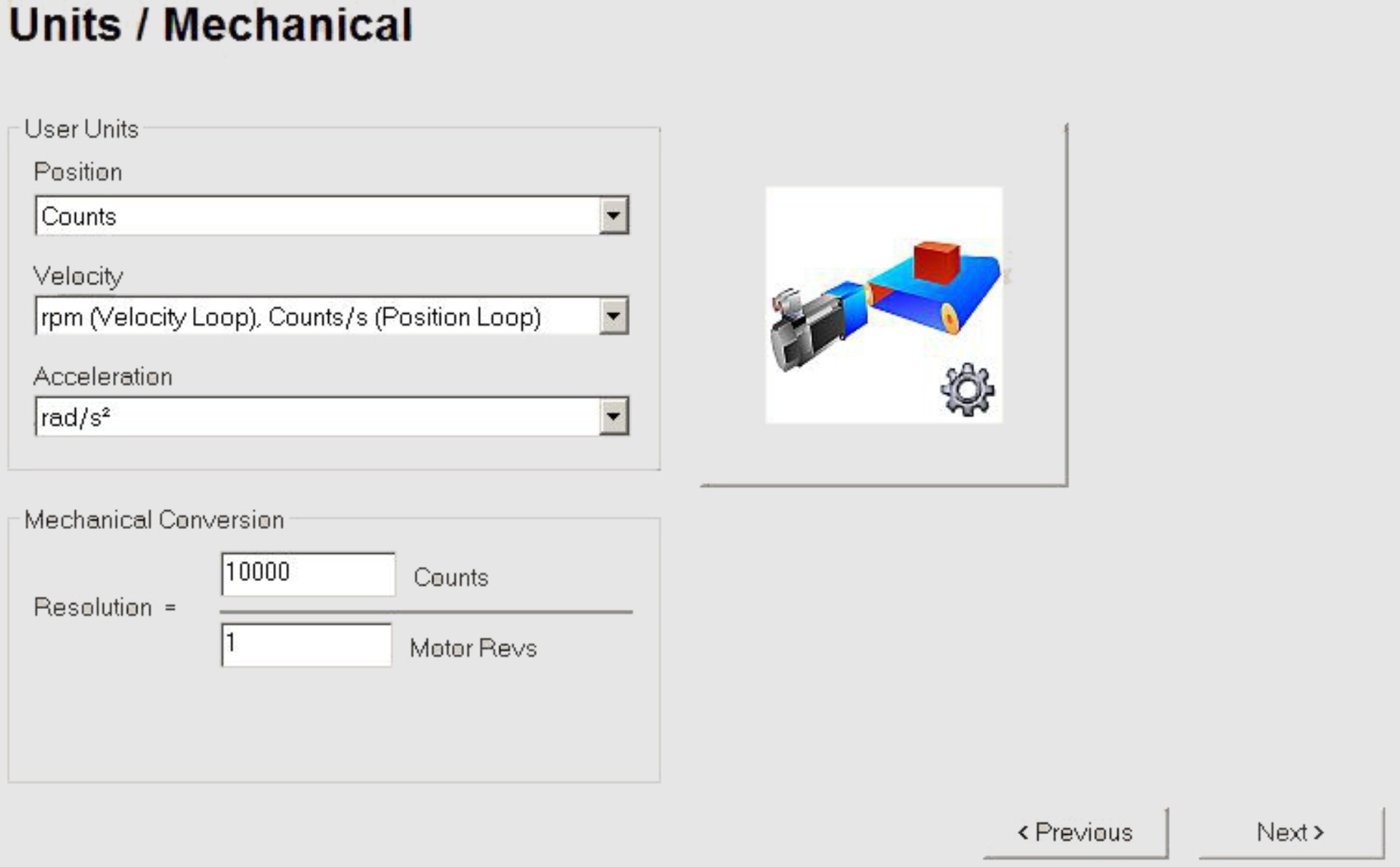
The user units for all input fields in the setup software can be preselected here.
|
Screen text |
ASCII Parameter |
|---|---|
|
Position |
|
|
Velocity |
|
|
Acceleration |
|
|
Position Loop Resolution (nominator) |
|
|
Position Loop Resolution (denominator) |
The adjustment of resolution depends on the application.
Click on the big button which shows the application graphics.
If your application does not correspond to any of the listed examples, enter the required parameters directly in the fields on the “Units” screen.
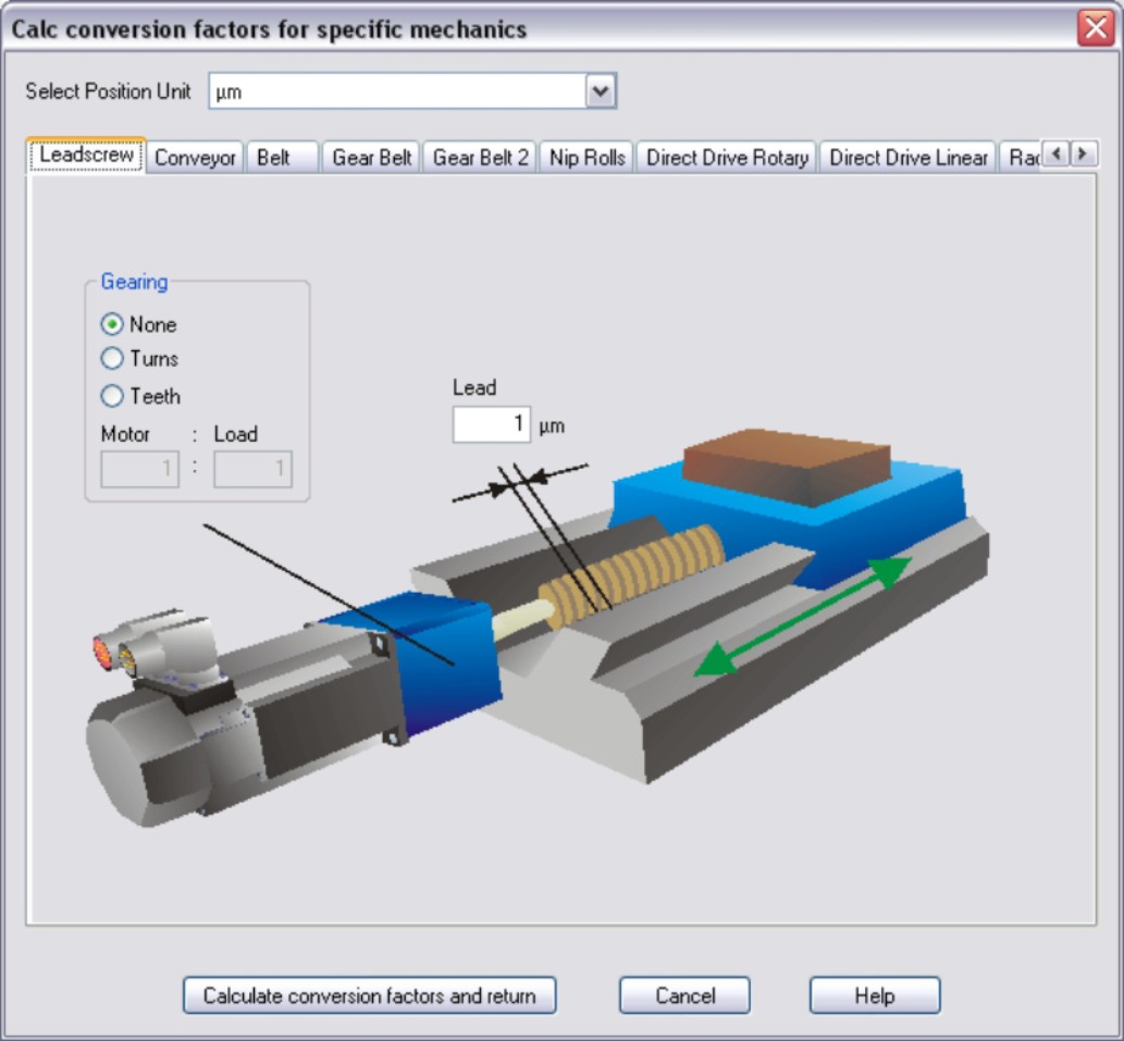
First, select the application that corresponds to your own. Next, set the position unit. Select the position unit that provides you with the required accuracy for your application.
Example
|
max. accuracy |
50nm |
|
Position unit |
10nm |
|
|
If you change the application type, the selected position unit may become impermissible. In such cases, the position-unit input window remains empty and you have to select a new unit. |
|
Leadscrew The load is driven via a lead screw. Enter the screw lead. If a gearbox is flange-mounted on the motor, you must also enter the gearbox data (either the number of teeth or the ratio of the revolutions). Then click the “Calculate conversion factors and return” button. |
|
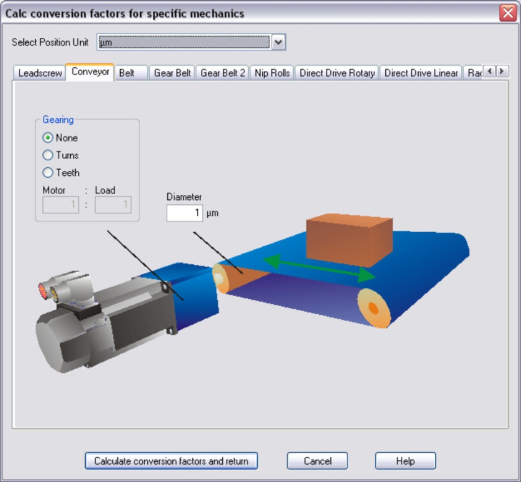
Conveyor Enter the driven shaft diameter. If a gearbox is flange-mounted on the motor, you must also enter the gearbox data (either the number of teeth or the ratio of the revolutions). Then click the “Calculate conversion factors and return” button. |
|
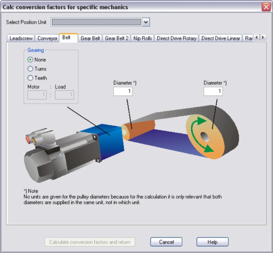
Belt Enter the driven- and output-shaft diameters. If a gearbox is flange-mounted on the motor, you must also enter the gearbox data (either the number of teeth or the ratio of the revolutions). Then click the “Calculate conversion factors and return” button. |
|
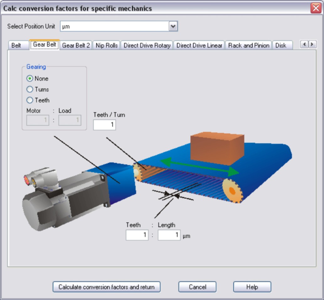
Gear Belt Enter the number of teeth per revolution of the driven gear wheel and the number of teeth per unit of length. If a gearbox is flange-mounted on the motor, you must also enter the gearbox data (either the number of teeth or the ratio of the revolutions). Then click the “Calculate conversion factors and return” button. |
|
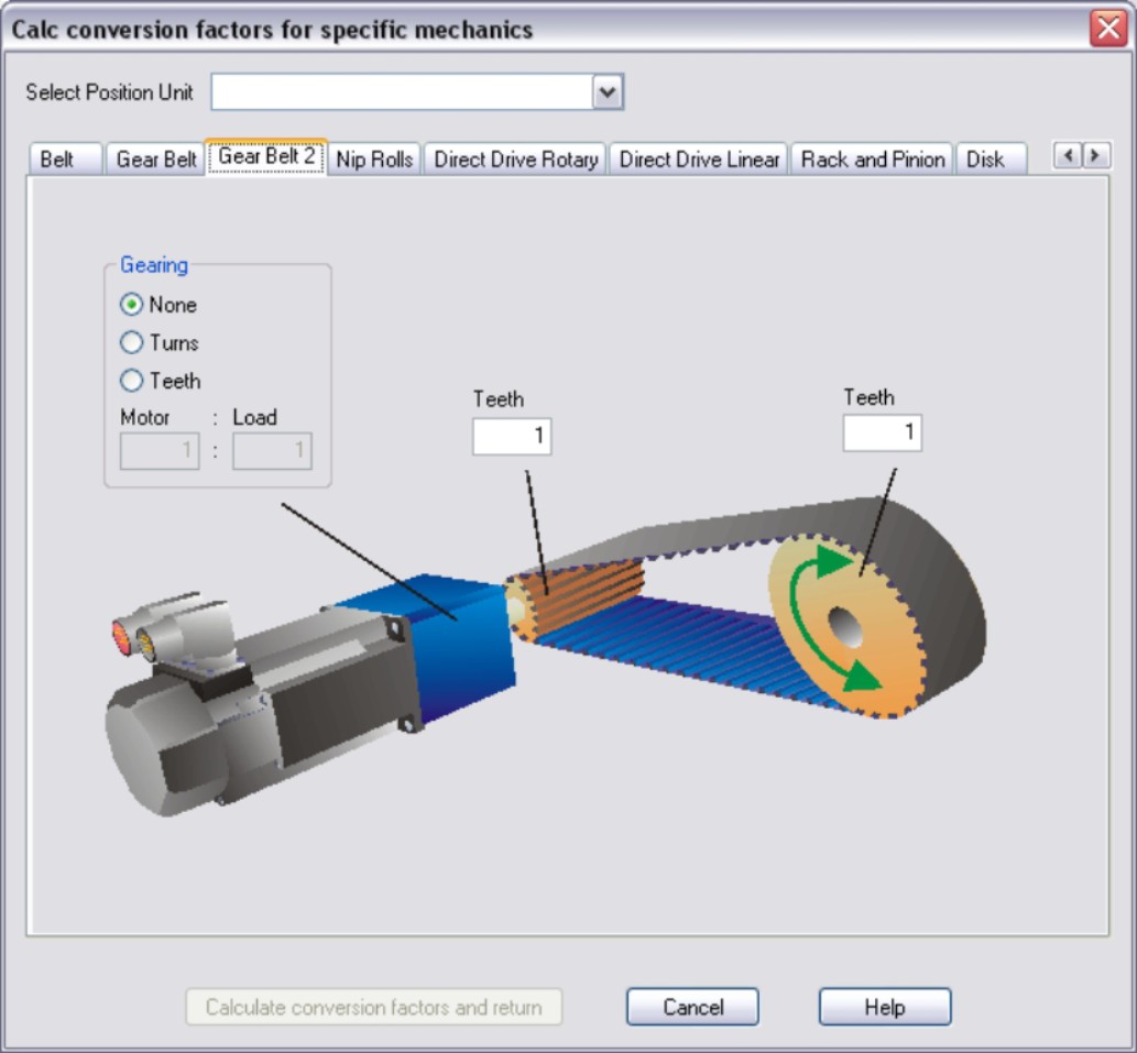
Gear Belt 2 Enter the number of teeth on the driven and output gear wheels. If a gearbox is flange-mounted on the motor, you must also enter the gearbox data (either the number of teeth or the ratio of the revolutions). Then click the “Calculate conversion factors and return” button. |
|
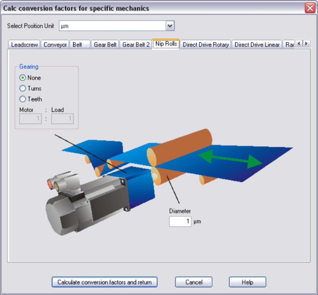
Nip Rolls Enter the driven shaft diameter. If a gearbox is flange-mounted on the motor, you must also enter the gearbox data (either the number of teeth or the ratio of the revolutions). Then click the “Calculate conversion factors and return” button. |
|
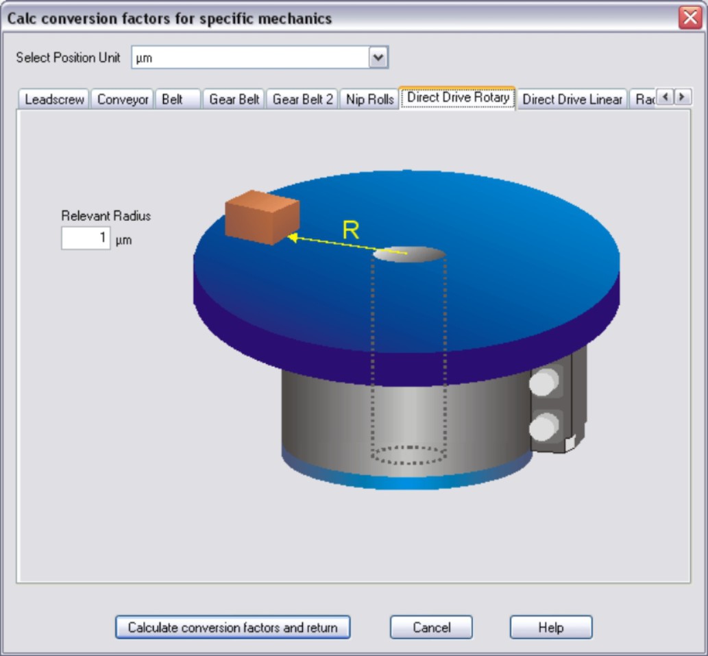
Direct Drive Rotary On selecting a length position unit, enter the appropriate radius for the route to be traversed. If the position unit is ° (degrees), you do not have to enter anything else. Then click the “Calculate conversion factors and return” button. |
|
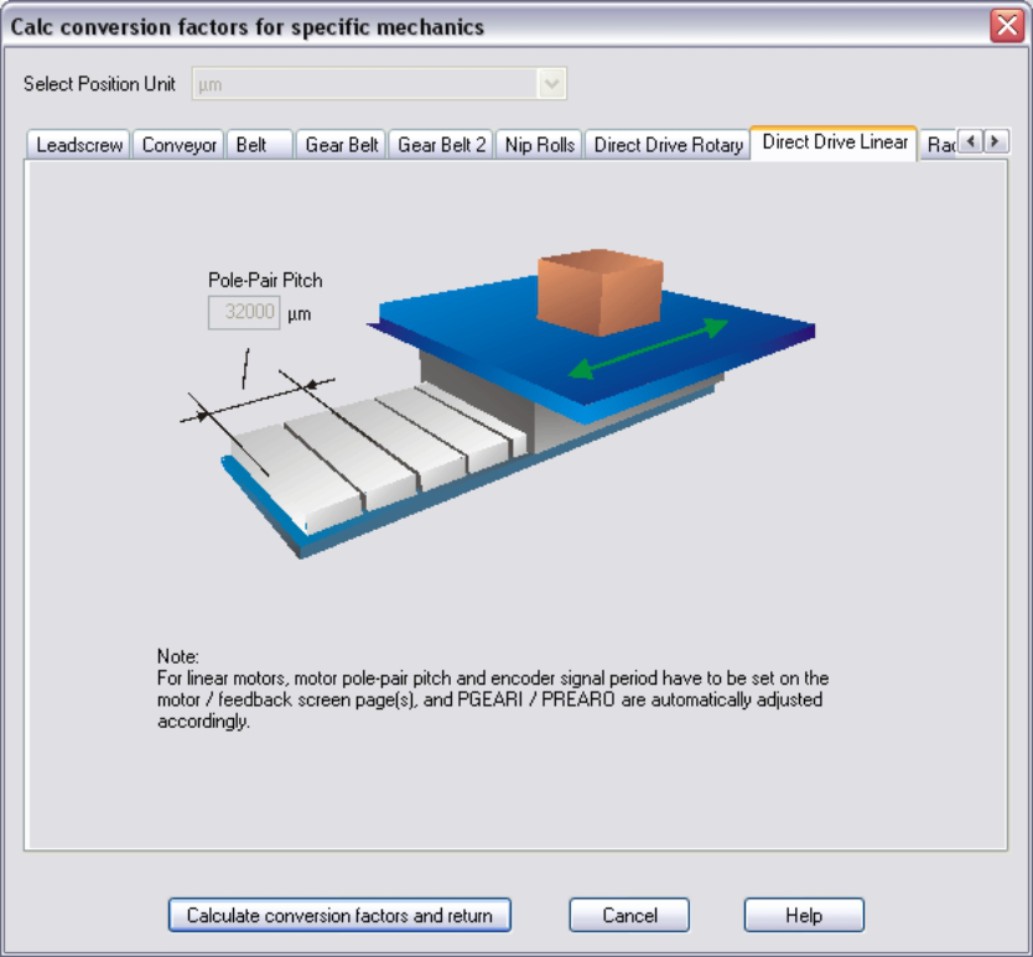
Direct Drive Linear The pole-pair width and encoder signal period depend on the device and are set on the Motor or Feedback screens. Then click the “Calculate conversion factors and return” button. |
|
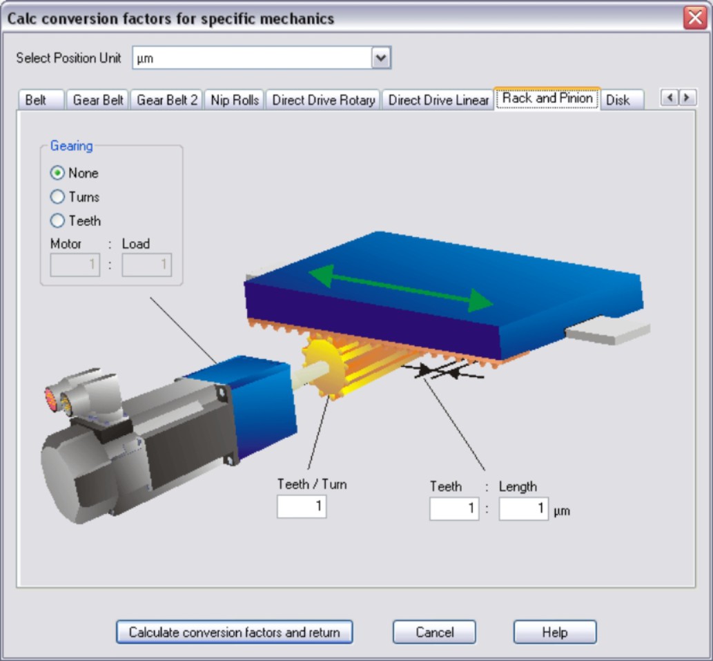
Rack and Pinion Enter the number of teeth per revolution of the driven gear wheel and the number of teeth per unit of length. If a gearbox is flange-mounted on the motor, you must also enter the gearbox data (either the number of teeth or the ratio of the revolutions). Then click the “Calculate conversion factors and return” button. |
|
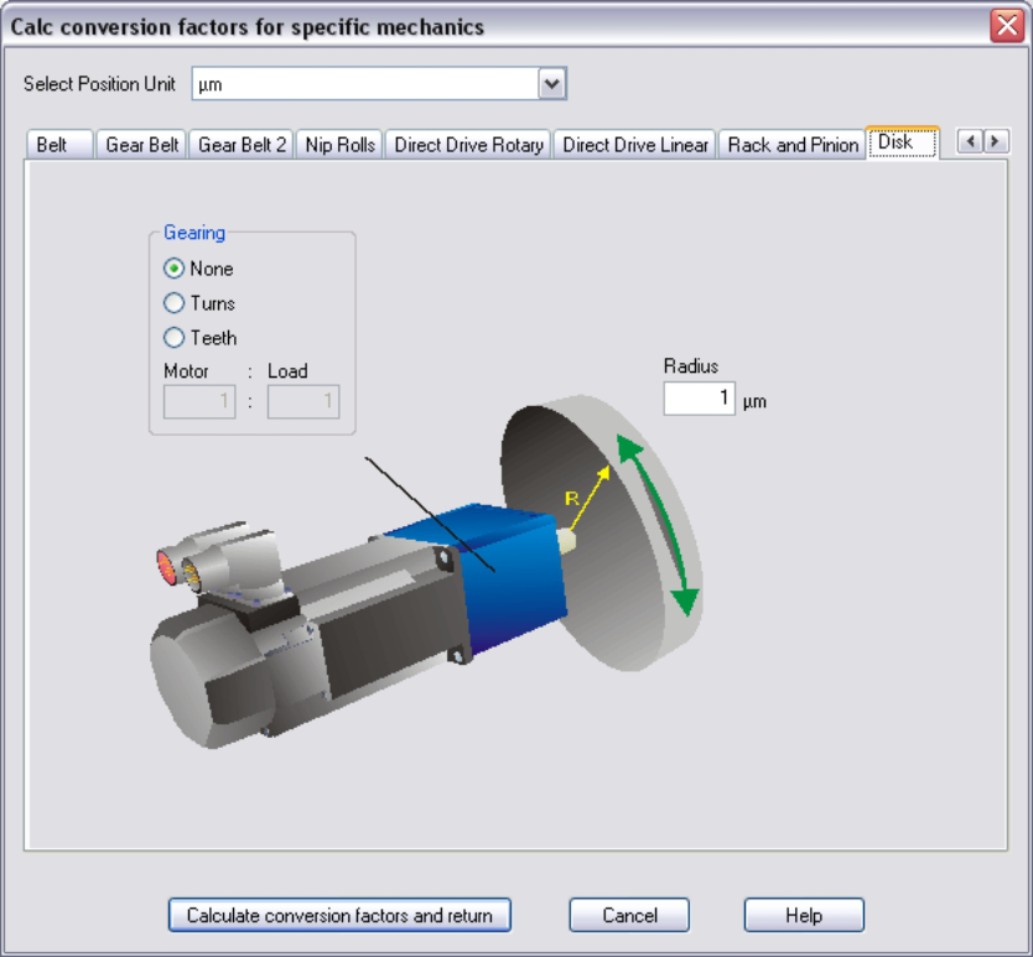
Disk Enter the radius of the mounted disk. If a gearbox is flange-mounted on the motor, you must also enter the gearbox data (either the number of teeth or the ratio of the revolutions). Then click the “Calculate conversion factors and return” button. |
|
Stay Connected with Kollmorgen       
|
Copyright © 2020 |
|