Test and diagnosis
Test Feedback/Motor
The feedback/motor test page offers a wiring test for the encoder or motor connection.
When the function is started in the current control mode (OPMODE = 2) with an enabled output, the motor slowly begins to turn. The movement is controlled without using the position encoder (U/F mode). The imported encoder position is observed and noted for evaluation purposes only. Using the position data, the encoder resolution, counting direction and encoder connection can be controlled. If the connection of the analog tracks is faulty, encoders that produce both digital as well as analog information (Endat2.1, Hiperface, BiSS-B) may sometimes lose positioning accuracy only. The drive can still be operated without any problems. Depending on the resolution of the encoder system, it can be difficult to detect such wiring errors.
This test function continually reads both the analog (if available) as well as the digital positional information of the encoder and checks the data for plausibility. If deviations occur, the test function tries to identify the cause of the problem.
The following parameters must be input correctly to ensure that the test can be carried out:
- Correct feedback type (FBTYPE)
- Correct parameters for the current control circuit
- Positive encoder counting direction (DIR=21)
- Correct number of motor pole pairs MPOLES

|
Risk of injury in case of vertical or pre-loaded load! The test works with reduced torque, therefore the testing of hanging load or pre-loaded load is not allowed. If possible, The test should be done without coupled load. |

Settings
- Number of revolutions (mechanical) - Specified travel path for the test movement. Since the movement occurs without sensors, it is important that the number of motor pole pairs is set correctly. Depending on the resolution of the encoder, at least one full mechanical rotation should be made.
- Current as % of nominal motor current - The sensorless operation mode requires a d-directional current (to generate a field). The d-current required for this is provided through this input.
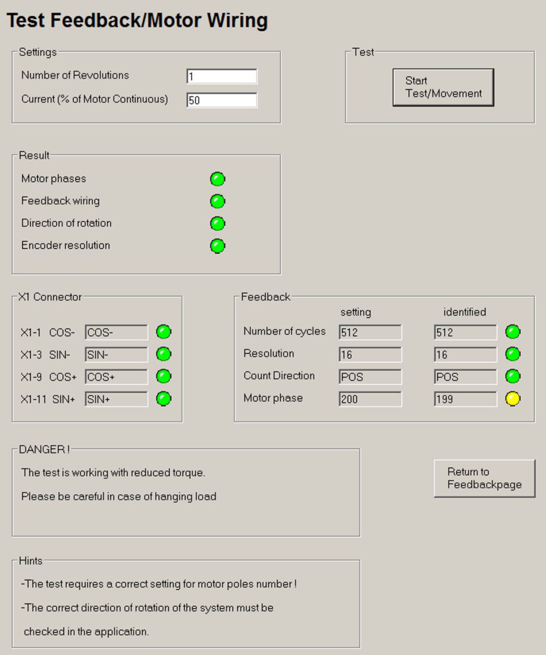
Result
The overall result of the test is displayed on this screen. For the individual tests, a green/red LED shows whether the respective test has been successful (green) or unsuccessful (red).
- Correct motor phasing – the travel path was successfully covered.
- Correct feedback – no feedback problem detected
- Correct rotational direction – the rotational direction of the encoder is positive - the analog and digital counting directions of an analog/digital encoder match.
- Correct encoder resolution – the detected resolution of the encoder does match the set values..
X1 Connector
This display only applies for encoders with analog and digital position measuring (Endat2.1, Hiperface, BiSS-B). Using the recorded positional information, the correlation between the analog and digital tracks is checked. If there is a discrepancy in the positional information, it may have been caused by interchanged X1 lines (sine/ cosine). The test function tries to detect the potential wiring errors and displays the result using the red or green LED.
Feedback – extended encoder information
This display only applies for encoders with analog and digital position measuring (Endat2.1, Hiperface, BiSS-B).
- Number of periods – number of sine/cosine periods per encoder rotation
- Resolution – number of counts (digital position) per sinus period (analog position)
- Counting direction – positive/negative counting direction
- Motor phase – a current motor phase is detected at the end of the test function. Should the detected value match the current MPHASE setting, the green LED turns on. If the value deviates by under 5 degrees, the yellow LED turns on, any higher and the red LED turns on. The result of the feedback/motor test can depend greatly on external influences.
Start the measurement procedure by clicking on the "Start Test/Movement" button.
Click on the “Return to Feedback Page” button to return to the feedback page.
Endat 2.2 Diagnosis
Contains up to 16 ENDAT2.2 encoder diagnose information. Diagnosis data has to be supported by the encoder and by the firmware (5.91 and newer) and configured in the drive (see ASCII command EN22CNFG). The meaning of the transmitted value can be found in the ENDAT encoder documentation delivered by the manufacturer.
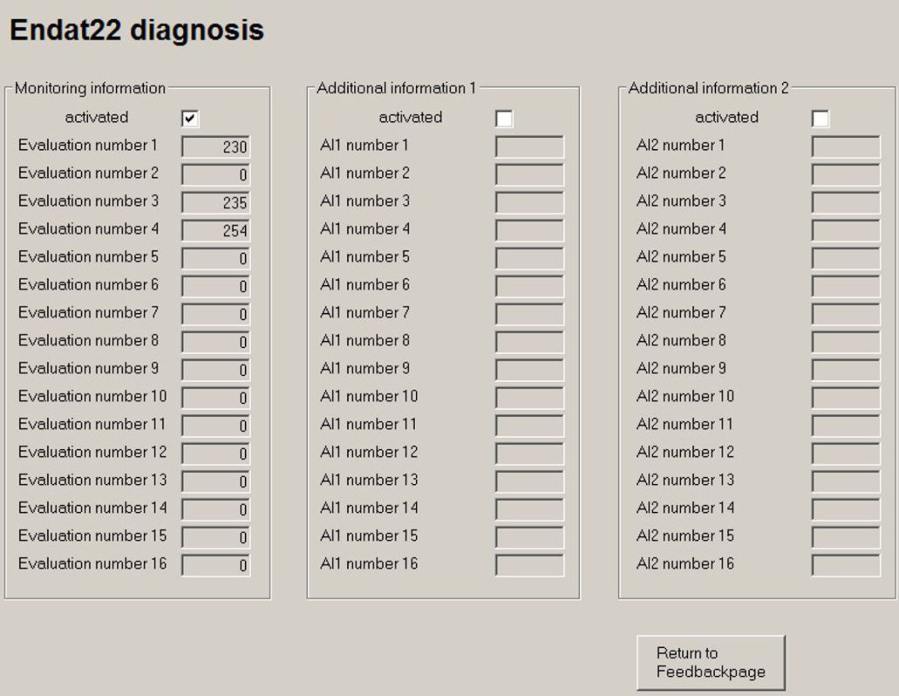
Monitoring Information
Contains up to 16 ENDAT2.2 encoder monitoring information. Diagnosis data has to be supported by the encoder and by the firmware and configured in the drive (see ASCII commands EN22CNFG and EN22DCNT).
Additional Information 1
Contains up to 16 ENDAT2.2 encoder additional information 1 (AI1). Diagnosis data has to be supported by the encoder and by the firmware and configured in the drive (see ASCII commands EN22CNFG and EN22A1CNT).
Additional Information 2
Contains up to 16 ENDAT2.2 encoder additional information 2 (AI2). Diagnosis data has to be supported by the encoder and by the firmware and configured in the drive (see ASCII commands EN22CNFG and EN22A2CNT).
HIPERFACE DSL Diagnosis
This page presents status information, which have been transmitted by the DSL Encoder.
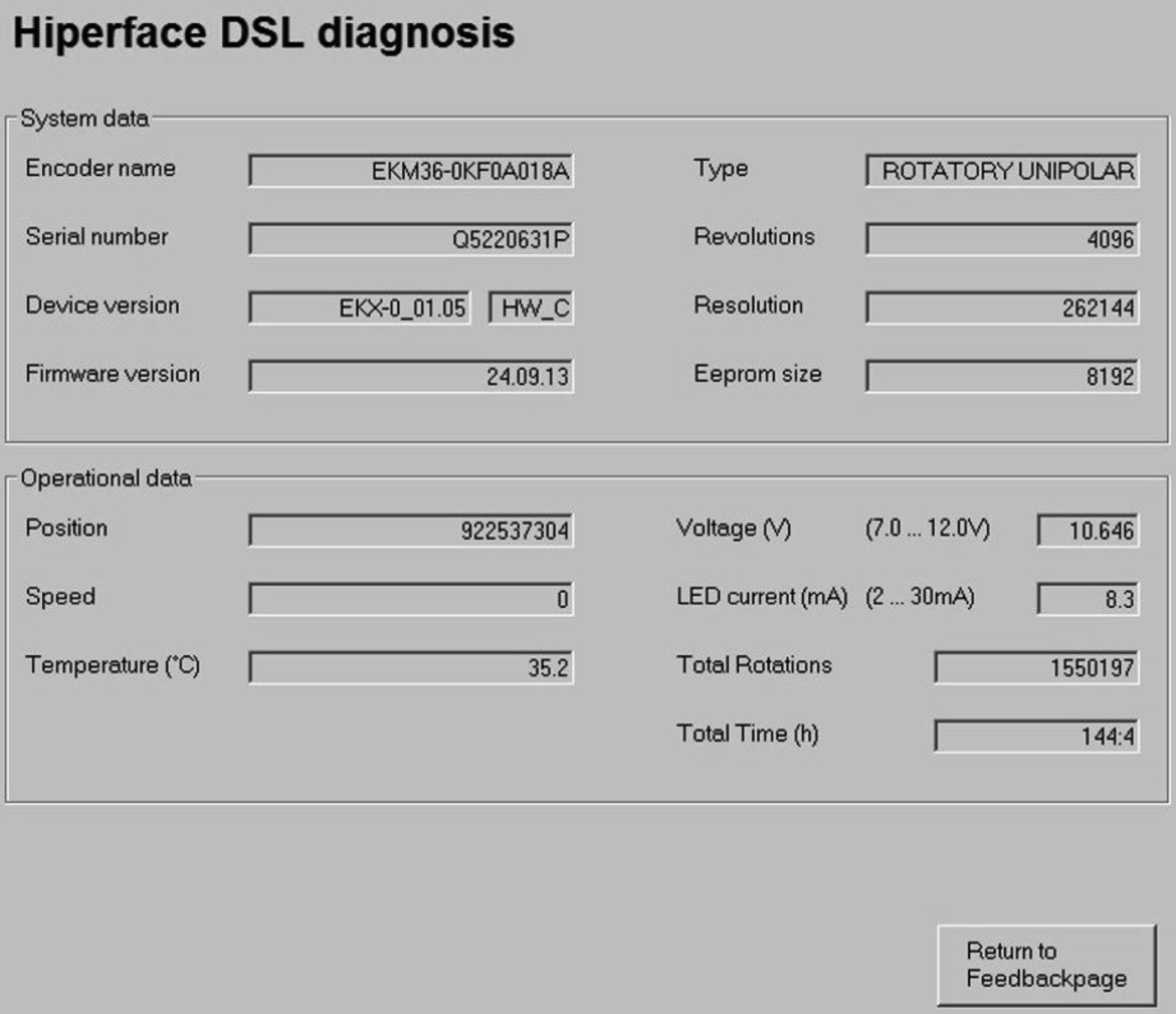
Click on the “Return to Feedback Page” button to return to the feedback page.


