| Feedback |
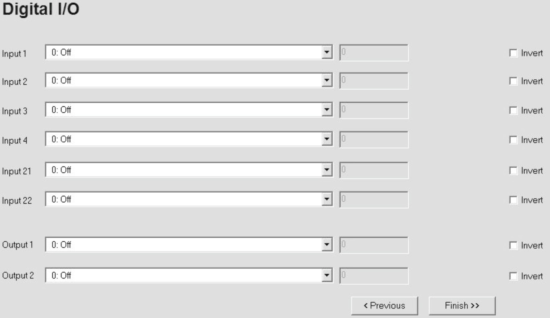
Assign predefined functions to the digital inputs and outputs of the servo amplifier.
Depending on the function, you can input a value or there is an additional button for an extended input screen.
Inputs 21/22 are available with S700 only. This servo amplifier offers two bi-directional interfaces, which can be used as input or output dependant on the selected function.The setting of these inputs are bolted with the correspondent outputs.
|
Screen text |
ASCII Parameter |
|---|---|
|
Input |
IN1MODE (Example for Input 1) |
|
Value |
IN1TRIG (Example for Input 1) |
|
Output |
O1MODE (Example for Input 1) |
|
Value |
O1TRIG (Example for Input 1) |
|
Invert |
DIRIN inverts the selected output function DIROUT inverts the selected output function |
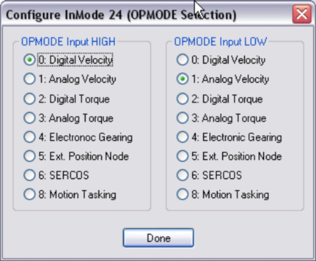
The operation mode of the servo amplifier is switched over by a digital input. The signal status (high or low) is evaluated. Select the OPMODE setting.
|
Screen text |
ASCII Parameter |
|---|---|
|
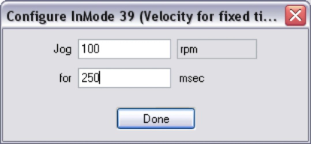
Jog |
IN1TRIG (Example for Input 1), bit 0...15 |
|
for time |
IN1TRIG (Example for Input 1), bit 16...31 |
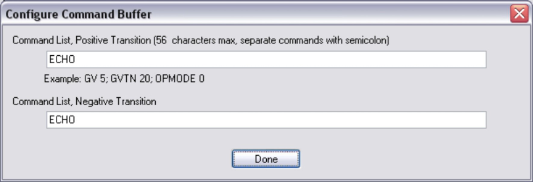
Input of the ASCII command list for execution. Depending on the edge of the input signal, the command lists can be different.
Application examples for using INxMODE30 can be found in the KDN (OPMODE switch over, screw drive functionality, velocity switch-over)
|
Screen text |
ASCII Parameter |
|---|---|
|
Command list, positive transition |
IN1HCMD (Example for Input 1) |
|
Command list, negative transition |
IN1LCMD (Example for Input 1) |
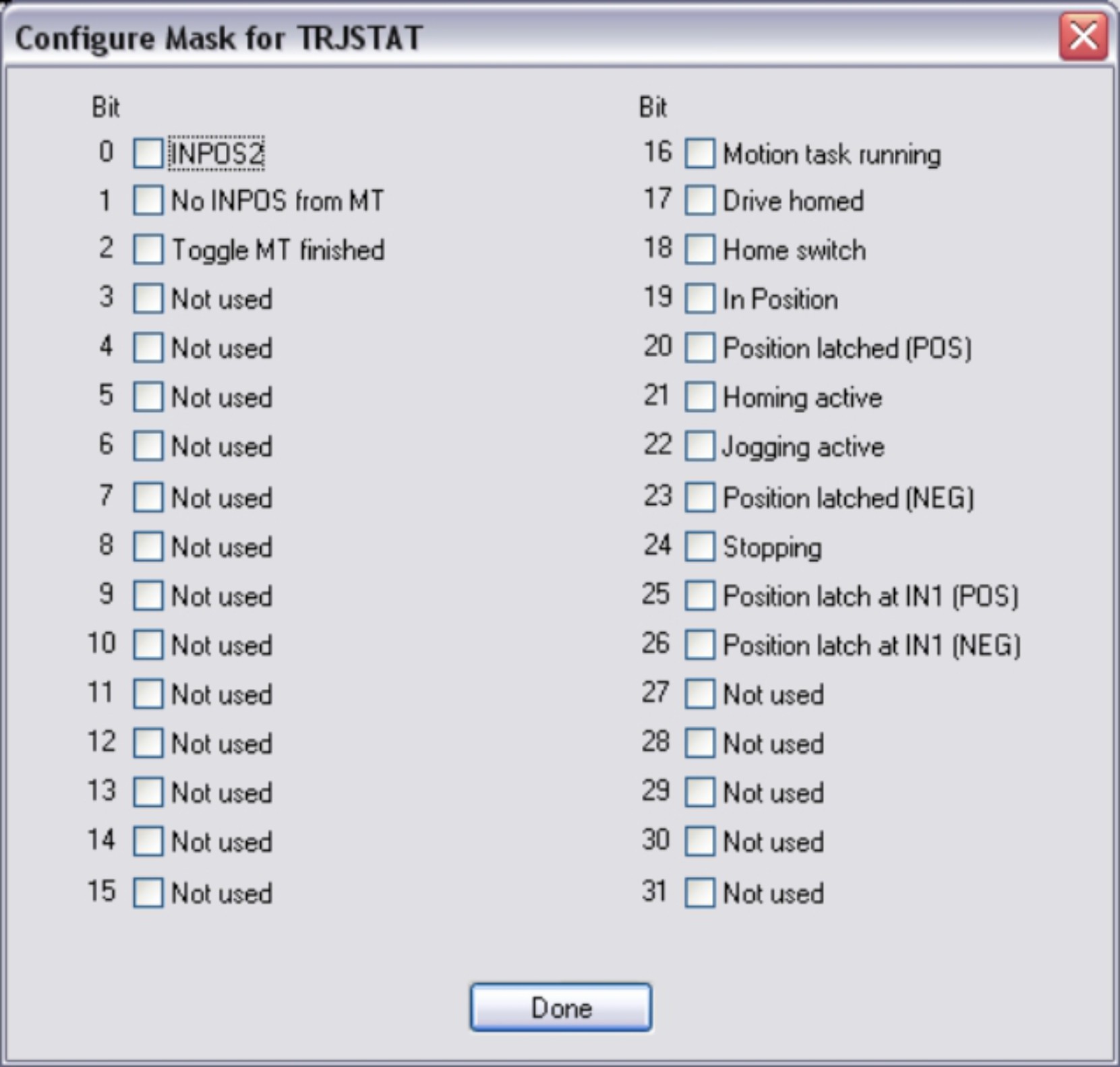
The command TRJSTAT returns the internal status information in the form of a bit-variable. The status information 3...15 and 27...31 are primarily used for internal functions. Bits 0...2 and 16...26 can be used for external functions (control system). Select the information in the bit mask that you want to observe. The bit mask is compared with the bit variable contents according to the selected logic (AND, OR, NAND, NOR). The digital output is set if the result is a logical 1.
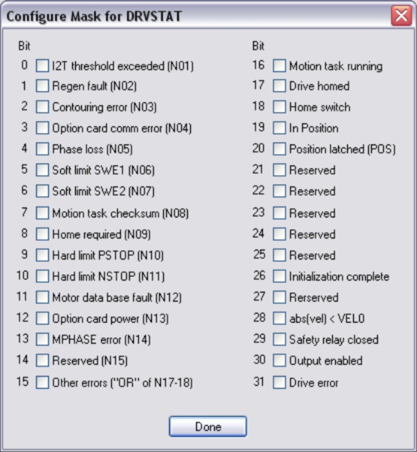
The command DRVSTAT returns the internal status information in the form of a bit-variable. Select the information in the bit mask that you want to observe. The bit mask is compared with the bit variable contents according to the selected logic (AND, OR, NAND, NOR). The digital output is set if the result is a logical 1.
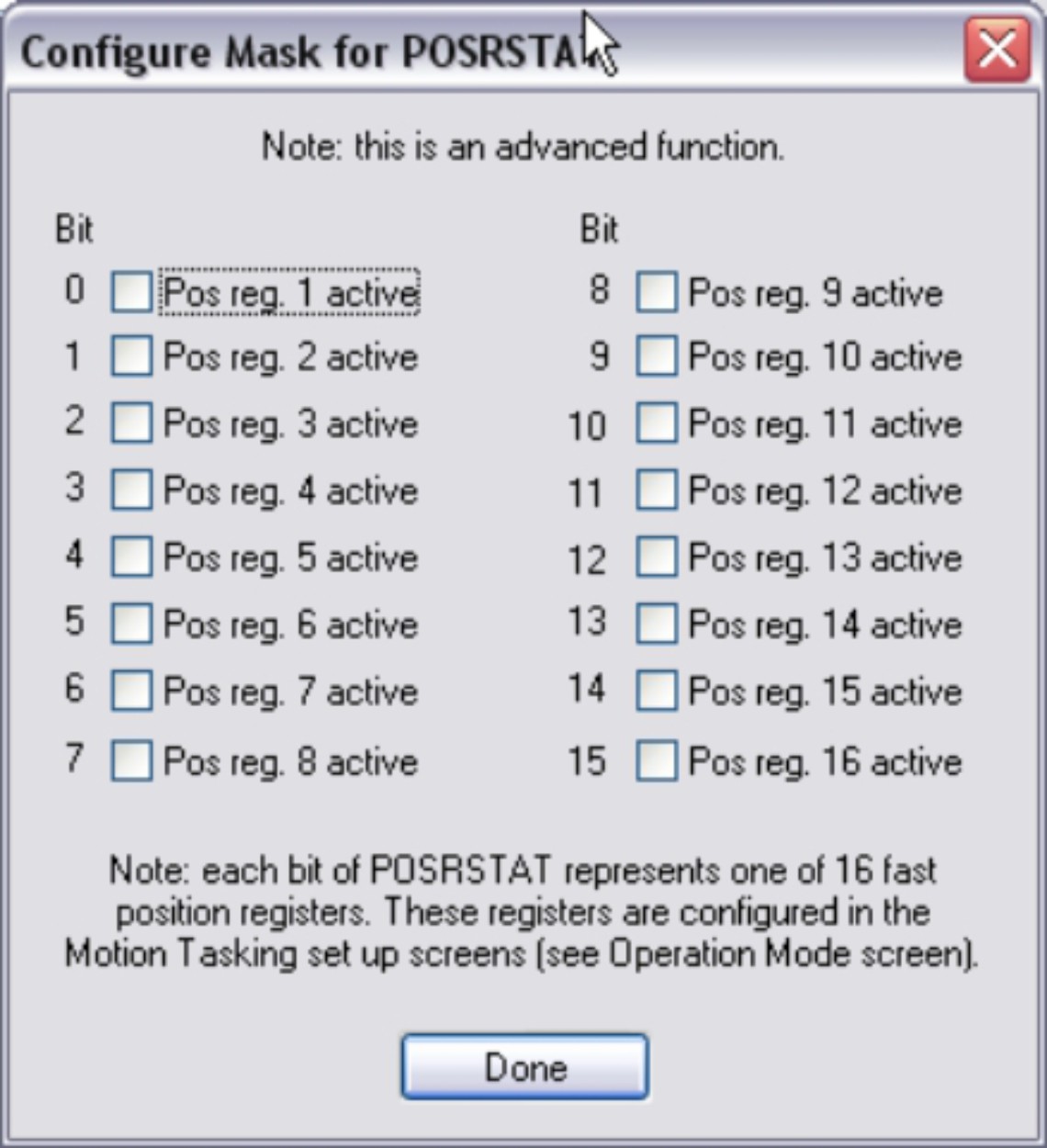
The command POSRSTAT returns the actual status of the fast position registers. Select the information in the bit mask that you want to observe. The bit mask is compared with the bit variable contents according to the selected logic (AND, OR). The digital output is set if the result is a logical 1.
|
Stay Connected with Kollmorgen       
|
Copyright © 2020 |
|
