|
|
|
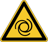
The motor shaft will rotate, the load will be moved! Risk of injury.
- Remove everything from the motion traverse.
- Don't touch the load when you proceed.
| Feedback |
Even without known motor and feedback data the drive can be configured. Set the parameters and functions in the terminal screen (commands are presented in italic font).
Steps 1...8: Without load (Motor shaft must be accessible)
|
Step |
Analyse / Set |
Description |
|---|---|---|
|
1 |
Brake / no brake |
Is it possible to turn the motor shaft manually (without gearbox or load)? => No: check if brake cable is connected to the servo amplifier MBRAKE 1 => Ja: MBRAKE 0 |
|
2 |
Direction of Feedback |
Open the Feedback Screen Turn the motor shaft clockwise with hand. (look to the front of the axis) Pointer rotate clockwise => OK Pointer rotate unclockwise => Change two signal wires of the feedback (SIN+ and SIN-). |
|
3 |
Resolver pole pairs / Encoder Enclines |
Open the Feedback Screen Turn the motor clockwise with hand. (look to the front of the axis) Check: One rotation of the motor shaft = one rotation of the pointer Yes => OK No => change MRESPOLES for Resolver / ENCLINES for Encoder and check again |
|
4 |
Motor pole pairs |
OPMODE 2 MPOLES 0 Switch on main power, set AS-Enable, set HW-Enable EN T 0.3 The motor shaft takes a preferential position. Turn the motor shaft manually. Count the steps (x=steps/turn) within one turn, every step is one pole pair. MPOLES x |
|
5 |
Commutation angle |
Danger! Don't touch the motor shaft! With the Zero command the offset angle is measured. OPMODE 2 EN ZERO ZERO ZERO SAVE HSAVE (for ENDAT and HIPERFACE feedbacks only) |
|
6 |
Direction of commutation |
OPMODE 2 EN T 0.1 T 0.2 T 0.3 ... T 0.n ... until motor shaft rotates slowly Clockwise => OK |
|
7 |
Smith Predictor |
Measure the phase-to-phase resistor (x in Ohm) and inductance (y in mH) values for the motor or take the values from the motor label. MRS x ML y K FILTMODE 2 SAVE COLDSTART |
|
8 |
Proportional Gain Current loop |
OPMODE 2 EN CTUNE |
Steps 9...14: With load

|
The motor shaft will rotate, the load will be moved! Risk of injury.
|
|
Step |
Analyse / Set |
Description |
|---|---|---|
|
9 |
Feedback Fine Tuning (Only for high precision systems) |
OPMODE 0 EN CALCRK CALCHP |
|
10 |
Observer Tuning |
OPMODE 0 EN OTUNE |
|
11 |
Proportional gain Velocity loop |
OPMODE 0 GVTN 0 EN STEP 500 50 500 –50 Open the oszilloscope screen and optimize the response of the actual speed to the setpoint change. Change GV in 20% steps until the response is best: GV 1 GV 1.2 GV 1.4 ... |
|
12 |
Integral gain Velocity loop |
OPMODE 0 GVTN 30 EN STEP 500 50 500 –50 Open the oszilloscope screen and optimize the response of the actual speed to the setpoint change by changing GVTN in 20% steps GVTN 30 GVTN 25 GVTN 20 ... |
|
13 |
Bode Plot |
Check the application for resonance (see screen page Bode Plot). |
|
14 |
Proportional gain Position loop |
Define two motion task in position loop with identical distance but contrary direction. (one task starts the other) OPMODE 8 EN MOVE X Open the oszilloscope screen and minimize the following error by changing GP in 20% steps GP 0.1 GP 0.15 GP 0.2 … SAVE |
Simple Sensorless Control for Induction Machines (Constant V/f Feed Forward Control). Hints for setup can be found in the KDN.
Direct current drives need special adjustments and connections for the operation at the servoamplifier, due to their constructive differences. The servoamplifiers require special adjustments and wiring to run a DC motor (with brushes) due to construction differences of a DC motor.
Hints for setup can be found in the KDN.
|
Copyright © 2020 |