| Feedback |
For each positioning task, you must define motion tasks. These motion tasks are selected by a motion task number and stored in the servo amplifier.
|
Motion task No. |
Memory |
Preassumption |
Note |
|---|---|---|---|
|
1...200 |
EEPROM |
Output stage disabled |
permanently stored |
|
201...300 |
RAM |
none |
volatile storage |
When the servo amplifier is switched on, the RAM motion blocks 201...300 are automatically pre-loaded with the parameters of the EEPROM motion blocks 1...100.
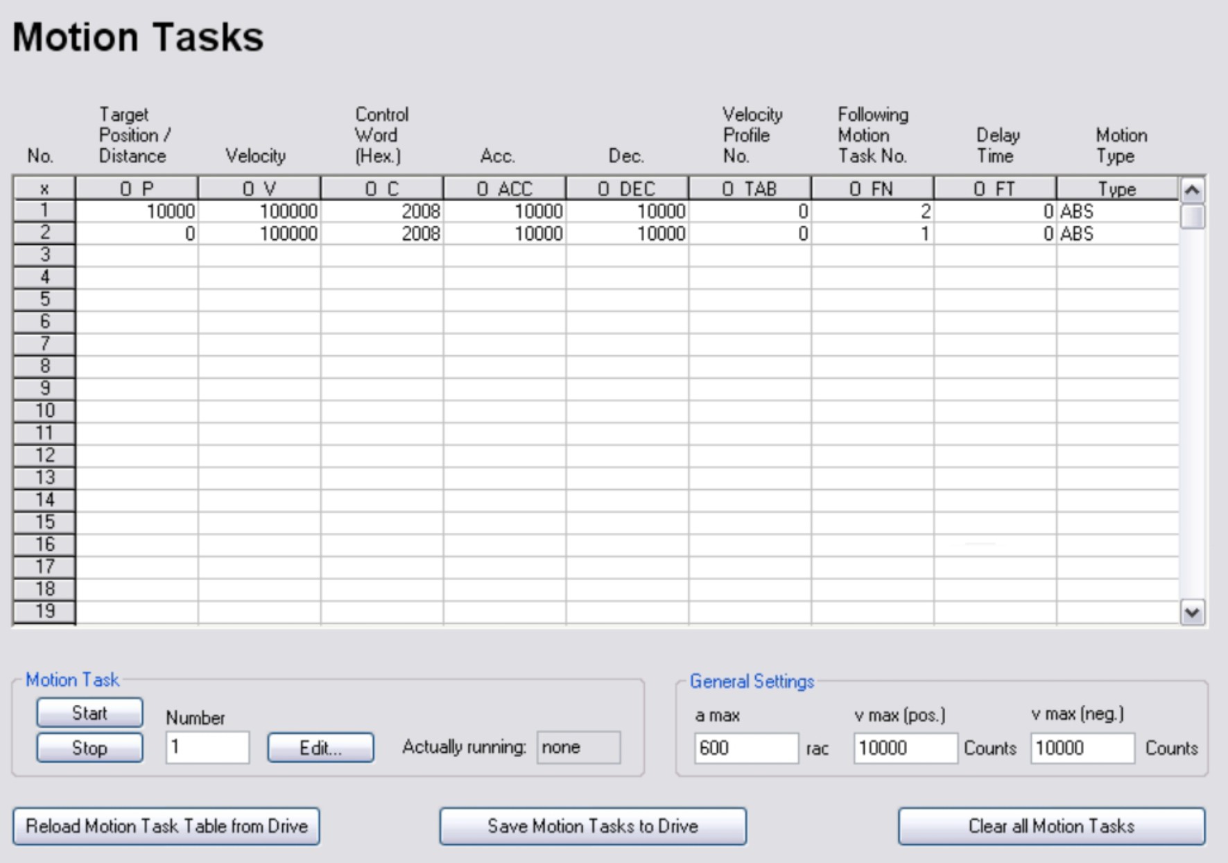
All motion tasks are represented in tabular form. All motion task parameters can be entered in the table directly. The standard Windows operations are available (Cut, Copy, Paste, Delete).
The clipboard operations cut, copy and paste are only possible for complete rows so, for these operations, the appropriate row must be selected. Deletion is possible, both row- and cellwise. A line can be selected either by clicking on the row number, or through the keyboard shortcuts <Shitft>+<Space> (similar to Microsoft Excel).
Double-clicking a line number in the table opens the screen page for the associated motion task.
|
|
The SW-enable is automatically set when the motion task starts. The motion task is only started in OPMODE 8. However, the SW-enable is set in all OPMODES. The drive can be accelerated by an analog setpoint that is applied, if the START command is executed in OPMODE 1 or 3. The motion task is not started if the target position is beyond the defined SW-limit switches (warning messages n06/n07 and n08). |
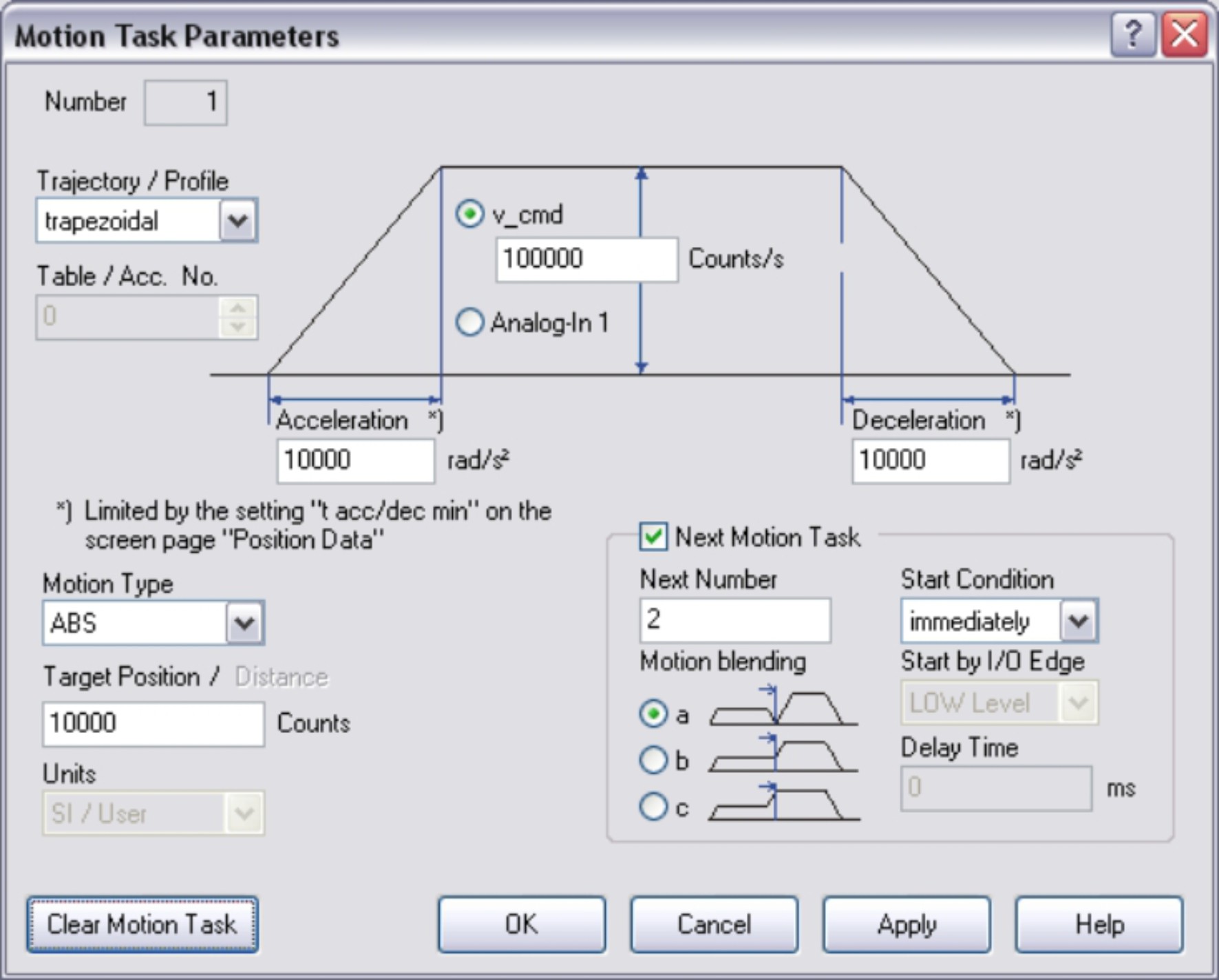
Number
Anzeige des aktuellen Fahrauftrags zur Bearbeitung.
Trajectory/Profile (O_C)
Determines which type of acceleration/braking ramp is used to carry out a motion task. Depending on the used profile a higher peak power of the amplifier is
| trapezoidal | The drive is given a constant linear acceleration/deceleration to the target speed. |
| table | The acceleration/braking ramps can be adjusted with a customer profile stored previously in the servo amplifier. |
| Beschl.(acc. (sine²) ²) |
To limit any jolting, the drive is accelerated/decelerated within the acceleration time along an acceleration ramp without any disruptions. The resulting speed characteristic corresponds to a sine² curve. The profile is stored in a table in the servo amplifier. |
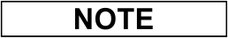
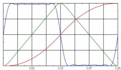
Table / Acc. No. (O_TAB)
Selection of a velocity profile from the table selected by trajectory.
Integrated profile tables:
IPx= Ipeak factor x: profile requires x% more peak current of the servo amplifier
I2tx= I2t factor y: profile requires y% more peak charge of the servo amplifier
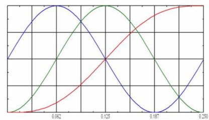
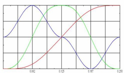
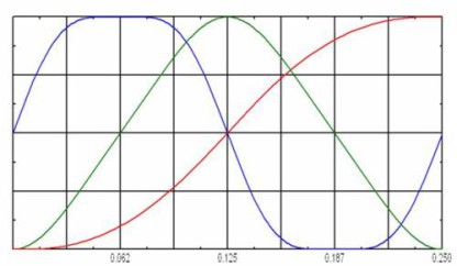
ret : P_cmd (position set point)
green: v_cmd (velocity set point)
blue: I_cmd (torque set point)
|
0 |
IPx 157% I2tx 123% |
|
|
1 |
IPx 200% I2tx 150% |
|
|
2 |
IPx 132% I2tx 115% |
|
|
3 |
IPx 113% I2tx 106% |
|
|
4...15 |
unused |
Customer specific tables with totally 4000 points possible |
v_cmd (O_V)
This parameter determines the velocity of movement for digital setpoint provision. If v_max is set to a value less than v_cmd at a later time, the position controller uses the smaller value.
Analog In 1
Analog setpoint provision at input An In 1 (terminals X3/4-5, is used. The value is read at the start of the motion task.
Acceleration (O_ACC)
This parameter determines the acceleration ramp steepness, depending on the selected units.
Deceleration (O_DEC)
This parameter determines the deceleration ramp steepness, depending on the selected unit.
Motion Type (O_C)
This selection determines whether the motion task is interpreted as a relative or an absolute task.
| ABS |
movement to an absolute target position, relative to the reference point. |
| REL cmd |
relative to last target (setpoint) position (in connection with motion block changeover: e.g., summing operation) |
| REL act |
relative to actual position at start (in connection with motion block changeover: e.g., register control) |
| REL In-Pos |
when the load is in the InPosition window: relative to last target position when the load is not in the InPosition window: relative to actual position at start |
| REL Latch pos. |
Contact our Customer Support |
| REL Latch neg. |
Contact our Customer Support |
Target position / Distance (O_P)
This parameter defines the distance or the target position, depending on the motion type.
Units
Unit for path and speed entries. See screen page "Units/Mechanical".
Select whether a new motion task should be started automatically, after the present task is complete. The InPosition signal is only enabled when the last motion task (no further task) is processed.
You can use the output function "16, Next-InPos" to generate a signal at a digital output when each target position within a sequence of motion tasks has been reached.
Next Number
The number of the next task, which starts automatically after the current task is complete.
Start Condition (O_C)
| immediately |
The next task is started as soon as the target position is reached. |
| I/O |
The next task is started by a signal at a digital input. This is only meaningful with "Motion blending type a". Condition: the digital input must have the function "15, Start next Motion Task" assigned, and the target position must have been reached. You can preselect the logic using the "Start with" parameter. |
| Time |
The next task is started with a defined delay after the target position has been reached. You can enter the delay time using the "Delay time" parameter. This is only meaningful with "Motion blending type a". |
| I/O or Time |
The next task is started by a signal at a digital input or after a defined delay. This is only meaningful with "Motion blending type a". The trigger is the event that occurs first (the start signal or the end of the delay time) Condition: the digital input must have the function "15, Start next Motion Task" assigned, and the target position must have been reached. You can preselect the logic using the "Start with" parameter, and enter the delay time using the "Delay time" parameter. |
Start by I/O edge (O_C)
The logic for the digital input that has the function "15, Start next Motion Task" assigned to it.
LOW-level: 0 ... 7 V
HIGH-level: 12 ...3 0 V / 7 mA
Delay Time (O_FT)
The entry (in ms) for the delay time between reaching the target position and starting the next task.
Motion blending
Select the action to be taken when the target position for the present motion task is reached.
| a |
The drive brakes to a stop in the target position. The next motion task is started. |
| b |
The drive moves at v_cmd of the present motion task to the target position, and accelerates through to v_cmd of the next task. |
| c |
The changeover to the next task is brought so far forward that the v_cmd of the next task is already reached by the time the target of the present motion task is reached. |
Clear Motion Tasks
Deletes the motion task from the table.
|
Stay Connected with Kollmorgen       
|
Copyright © 2020 |
|