| Feedback |
This function is independent from the used firmware version. It can be used in offline or online mode.
Click and hold the left mouse button in the curve area. Drag the mouse to create a zoom rectangle.
When the mouse button is released, the selected rectangle is enlarged to the entire display area. A short click of the right mouse button deactivates the zoom function and displays the entire curve. If the data cursor is placed in the zoomed area when the zoom is active, then the left / right arrow keys can be used to move the zoom area within the entire curve. Use the arrow down / up or the mouse wheel to stretch or compress the range of the time axis around the data cursor.
Click the left mouse button on the channel text (for example, channel 2) to hide the associated curve. The channel text “Channel 2" is replaced by ”—-". Clicking the left mouse button again unhide the curve of the corresponding channel.
By clicking the right mouse button on the channel text, all channels except the selected channel are hided (solo display). Clicking the right mouse button again on the solo channel will unhide all curves.
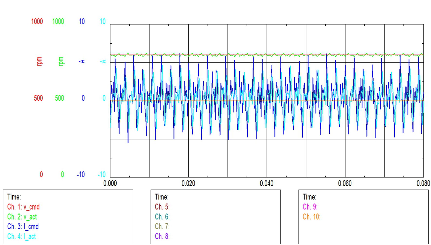
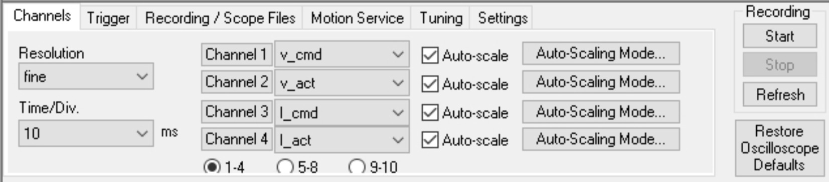
Up to 10 channels can be displayed and/or recorded simultaneously in the Scope window and saved as an Excel file. The configuration is done in groups of 4. The group 1-4, 5-9 and 9-10 are chosen via "radio buttons" below the channel names.
Cycle time for the measurement acquisition ≥ 250 µs.
Resolution
The number of measured points per time unit (storage depth). Setting: fine, normal, coarse
Time/Div
Scaling of the time axis. Select the time/division. Setting: 1 ... 5000 ms/div
Total length of the time axis: 8 * x ms/Div
Channel #
Assignment of the displayed variables to the channels.
|
I_act |
Actual torque (current) |
|
I_cmd |
Torque setpoint |
|
n_act |
Actual velocity |
|
n_cmd |
Velocity setpoint |
|
S_act |
Actual position |
|
S_cmd |
Position setpoint |
|
PERROR |
Position error |
|
VBUS |
DC-link (bus) voltage |
|
Off |
Channel is not used |
|
user-defined |
Macro Variable |
If you select "user-defined" you can display the value of a MACRO parameter. For channel 4 for example this screen appears:
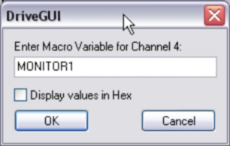
Fill in the macro variable name (see selection of macro variables below).
|
Macro Variable (selection) |
Short Description |
|---|---|
|
ERRCODE |
Error state variable (see ERRCODE) |
|
STATCODE |
Drive state variable (see STATCODE) |
|
TRJSTAT |
Trajectory state variable (see TRJSTAT) |
|
ADVAL0…15 |
Analog input values |
|
ADVAL0 |
Cosine Resolver |
|
ADVAL1 |
Sine Resolver |
|
ADVAL2 |
Motor current Ia |
|
ADVAL3 |
Motor current Ib |
|
ADVAL4 |
Sine Encoder |
|
ADVAL5 |
Cosine Encoder |
|
ADVAL6 |
Analog setpoint 1 |
|
ADVAL7 |
Analog setpoint 2 |
|
ADVAL8 |
Motor temperature |
|
ADVAL9 |
Heatsink temperature |
|
ADVAL10 |
Environments temperature |
|
ADVAL11 |
Sense voltage encoder |
|
ADVAL12 |
n.c. |
|
ADVAL13 |
DC bus link voltage |
|
ADVAL14 |
n.c. |
|
ADVAL15 |
n.c. |
|
SIENC |
Normalised sine encoder +/- 1350 <> 1Vss |
|
COENC |
Normalised cosine encoder +/- 1350 <> 1Vss |
|
SR_RXDE |
Zero pulse port for NREF = 5 |
|
SR_HALL |
Hall segments port |
|
PFBL |
Position Feedback 64 Bit size. The lower 32 bits includes the position within a revolution, the upper 32 bits counts the number of revolutions. |
|
S_SETL |
Position setpoint 64 Bit size. The lower 32 bits includes the position within a revolution, the upper 32 bits counts the number of revolutions. |
|
PFB |
Position Feedback (PRBASE size) |
|
S_SET |
Position setpoint (PRBASE size) |
|
S_SETH |
Sercos position setpoint (1 Revolution = 2^20) |
|
PTARGET |
Target position for the last/current motion task (PRBASE size) |
|
PSPEED |
Actual velocity setpoint in counts/250µsec |
|
PSPEEDMS |
Actual velocity setpoint in counts/250µsec for master/slave trajectory |
|
PSPEED3 |
Actual velocity setpoint for internal motion task trajectory |
|
PENDSPEED |
End velocity setpoint for the actual motion task |
|
MOVEP_NR |
Number of the last/actual motion task |
|
NIZFLAG |
State of the external zero pulse |
|
PSTOP |
State of the PSTOP limit switch |
|
NSTOP |
State of the NSTOP limit switch |
|
INPUT1…20 |
State of the hardware/software input 1…20 |
|
OUTPUT1...18 |
State of the hardware/software output 1..18 |
|
HARDENA |
State of the hardware enable |
|
EN_P_I |
State of the power stage (1=enabled, 0=disabled) |
|
NET_BTBI |
State of the net BTB |
|
ENABLE_I |
State of the internal enable signal |
|
SOFTENABLE |
State of the software enable |
|
EN_BRAKE_I |
Brake state (1=open, 0=closed) |
|
PRD |
Feedback position within one turn |
|
IVORCMD |
Current feed forward (3280 = DIPEAK) |
|
PBAL |
Regenerative power actual value |
|
SR5VINCR |
Pulse counter for X5 Master / Slave (5V) |
|
SR24VINCR |
Pulse counter for X3 Master / Slave (24V) |
Auto-scale
For each channel the range of measurement can be selected: automatically (Auto checkbox is active) or manually (Auto checkbox is inactive, and min./max. values have been entered).
Auto-Scaling Mode
You can select standard or min/max scaling.
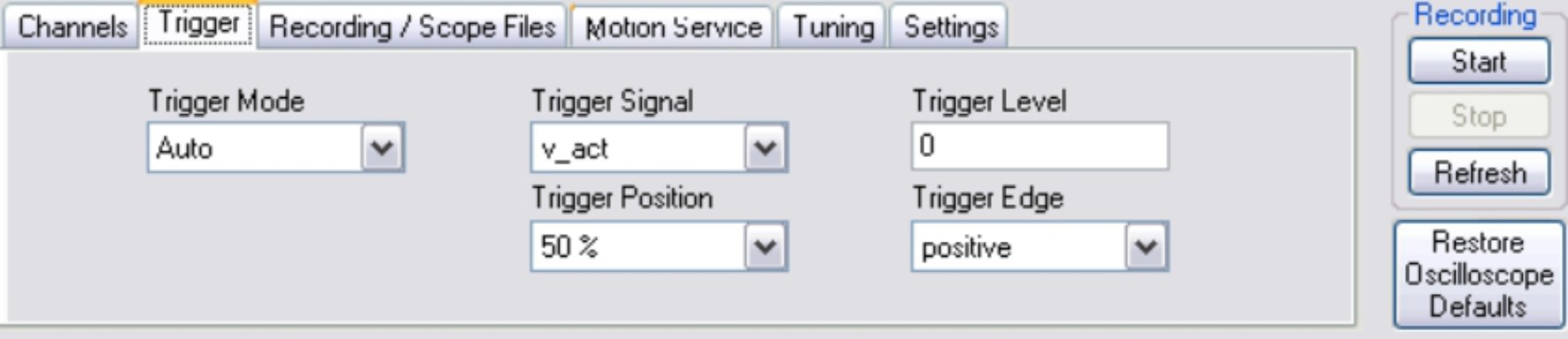
Trigger Mode
You can select standard or min/max scaling.
Trigger Signal
The current and speed variables can be used as trigger signals. In addition, "Direct" can be used for immediate (independent) triggering. The setting "user-defined" enables manual entry of an ASCII variable.
Trigger Position
X-value for triggering (time axis
Trigger Level
Y-value for triggering
Trigger Edge
Triggering on the rising or falling edge
Save
Saves the recorded measurements to a data medium in CSV format (to be evaluated with MS-Excel).
Load
Loads a CSV data file and displays the curves on the oscilloscope diagram.
Mem
If this is active when a new curve is recorded, the previous measurement is saved so a comparison can be made between the two measurements. The previous measurement curve is displayed in a darker color than the latest curve. The measurement range settings must be identical for both measurements. If not, the "Mem" checkbox is de-activated and locked.
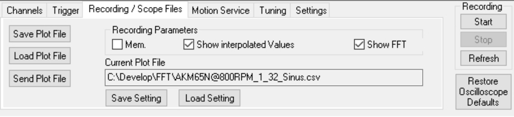
Show interpolated values
If the chackbox is activated, intermediate values between the mearured values are interpolated.
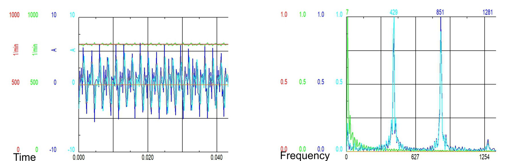
FFT
Setting a check mark replaces the time representation of the recorded curves with a frequency representation. The x-axis shows the frequency in Hz.
Current plot file
Displays the filename and location of a loaded CSV file.
Save Setting / Load Setting
Using the two fields, the scope settings can be saved in a file or read from a file. Stored data includes: channel names, ranges of values, resolution, and channel colors.
|
|
Be sure that the actual position of the load permits the subsequent positioning operations. The software limit-switches that were set as parameters are inactive, depending on the operation mode. The axis could move to the hardware limit-switch or even the mechanical stop. There is a risk of damage. |
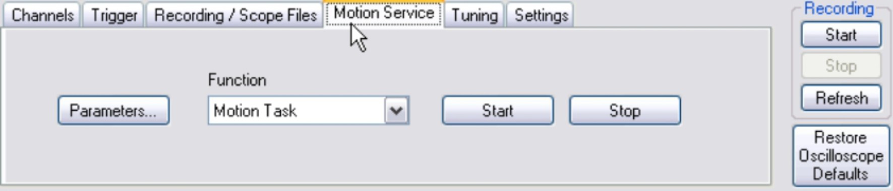
Function
Select one of the service functions described below. Click on the "Parameter" button and set the corresponding parameter. Start the function using the START button. The function continues until you click the STOP button or until you hit function key F11.
| Direct current |
Apply a direct current to the motor with adjustable size and electrical field-vector angle. The changeover from speed control to current control is made automatically. Commutation is made independently of the feedback (resolver or similar). The motor locks into a preferred position. |
||
| Speed |
Operates the drive at constant speed. An internal digital setpoint is provided (speed is adjustable). |
||
| Torque |
Operates the drive with constant current (constant acceleration). An internal digital setpoint is provided (current is adjustable). The changeover from speed control to current control is made automatically. Commutation is made independently of the feedback (resolver or similar). |
||
| Reversing |
Operates the drive in reversing mode, with separate adjustable speed and reversing time for each direction of rotation. |
||
| Motion Task |
Starts the motion task, which is selected on the screen page "Service Parameters" |
||
| Zero |
Function for the automatic setting of the feedback unit phase, according to the phase position of the motor. Operation mode switches to OPMODE 2 . |
||
|
|||
| Start / Stop |
Start / Stop the selected service function. Stop can be done with F11 as well. |
||
Parameter
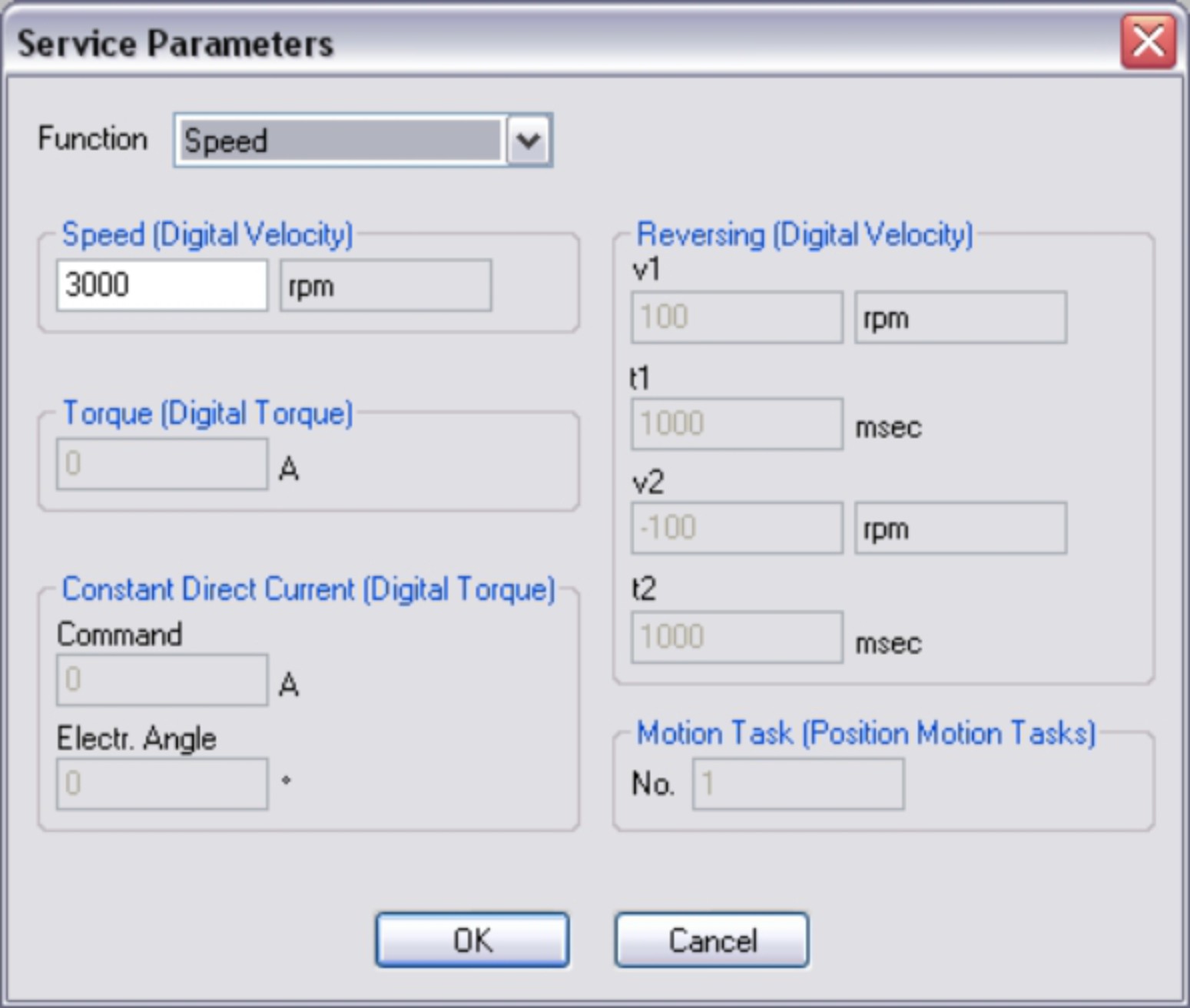
Adjust the service function parameters.
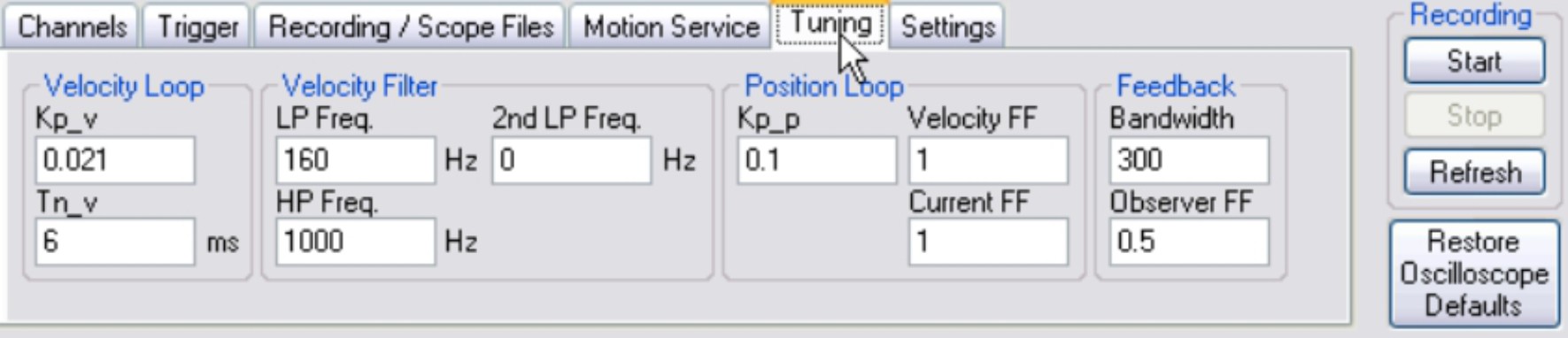
Some variables important for the control behavior are combined here. You can tune the servo amplifier without closing the oscilloscope screen page.
|
Kp_v |
|
|
Tn_v |
|
|
TP Freq. |
|
|
2. TP Freq. |
|
|
HP Freq. |
|
|
Kp_p |
|
|
Velocity FF |
|
|
Current FF |
|
|
Resolver BW |
|
|
Observer FF |
Basic setup for the scope can be done here.
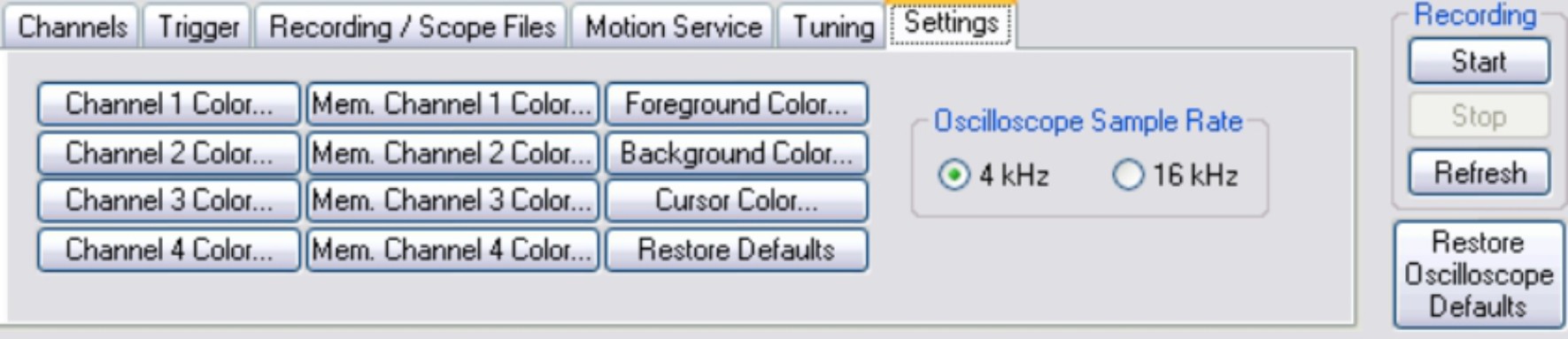
Colors can be defined for every channel, foreground, background and cursor. Click to the specific button opens the selection frame for colors:

Buttons "Mem. Channel x Color..." define the colors of the previous measurement curve. Click to "Restore Defaults" sets the colors back to manufacturer defaults.
|
Screen text |
ASCII Parameter |
|---|---|
|
Oscilloscope Sample Rate 4kHz/16kHz |
This tab only appears when the Wake and Shake control loop method is selected (see also the chapter Wake und Shake).
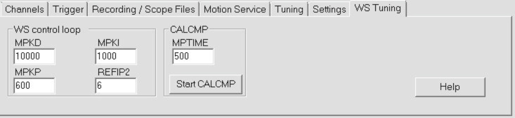
The “Start CALCMP” button initiates the Wake and Shake function.
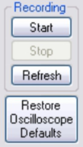
|
Start/Stop Start/stop of data recording Refresh Reloads and displays the last recorded scope data from the servo amplifier, if these are not deleted yet. Restore Oscilloscope Defaults Resets all functions of the screen page to the default values. |
Cursor functionality
When a data set is displayed (from a file, or by starting a recording), the measured values for the signals are displayed in the co-ordinate system for the selected time period by a mouse click. A click outside the coordinate system, or a click while pressing the shift-key, resets the values in the display to zero.
|
Stay Connected with Kollmorgen       
|
Copyright © 2020 |
|