| Feedback |
This screen is avalable only if a SERCOS expansion card is inserted into the servo amplifier.
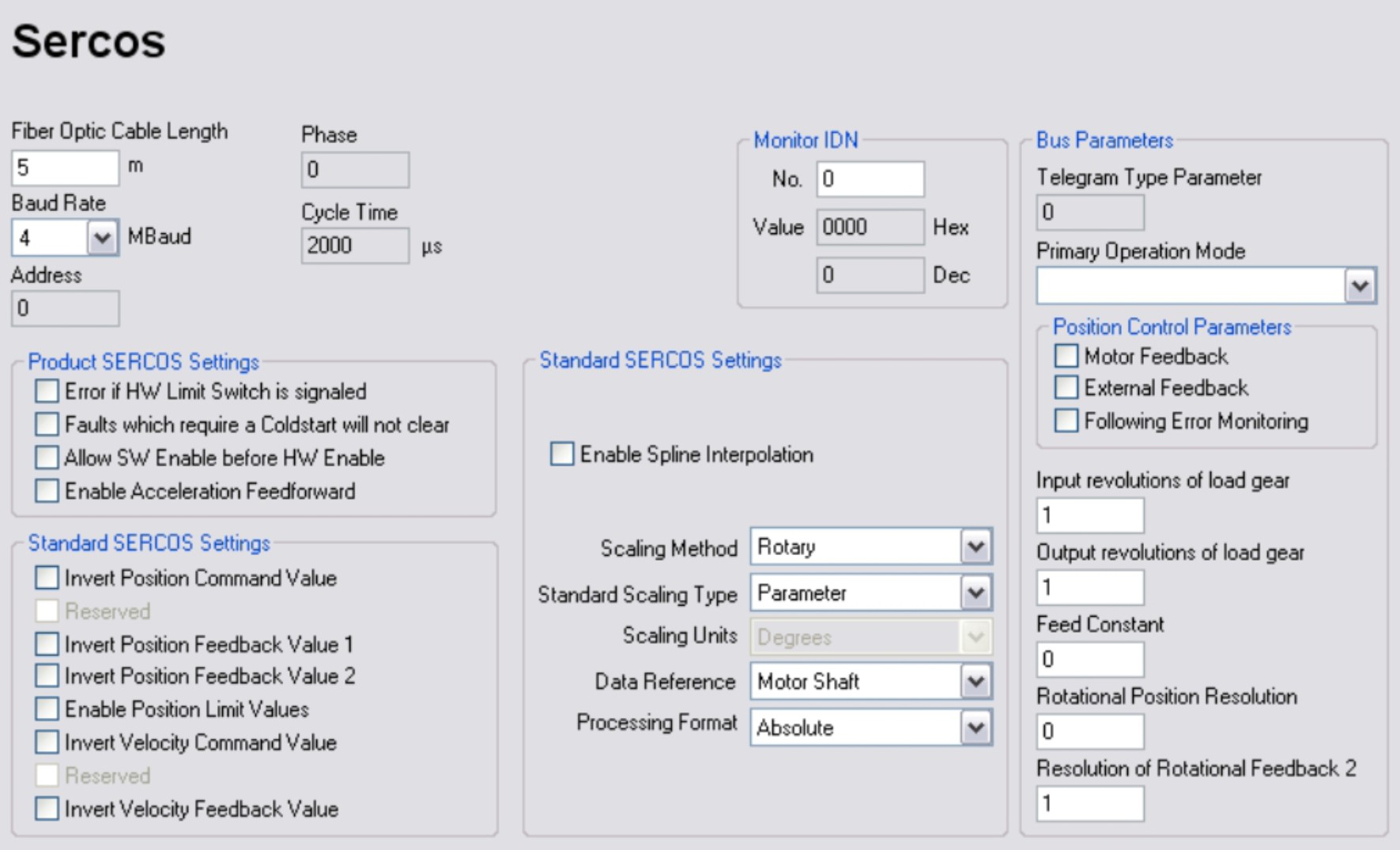
Configuration of the SERCOS interface for proper communication with the master.
Set the cable length (max. 45m, important for optical power) and the baud rate (see installation manual of the servo amplifier).
If the optical power is not adjusted properly, there will be errors in the telegram transmission, and the red error LED on the drive lights. In normal communication, the green transmit and receive LEDs flash very fast, the LEDs seem constantly lit.
For further information for installing a SERCOS system, see the SERCOS documentation and our application notes available on our website.
Fiber Optic Cable Length
If the optical power is not adjusted properly, there will be errors in the telegram transmission. You can define the cable length (in meter) for a standard 1 mm² fiber optic cable.
|
0 m |
Very short connection |
|
1 m…< 15 m |
Length of the connection with a 1 mm² plastic cable |
|
15 m…<30 m |
Length of the connection with a 1 mm² plastic cable |
|
≥ 30 m |
Length of the connection with a 1 mm² plastic cable |
Baud Rate
If the baud rate is not adjusted correctly, communication will not work. Adjust the baud rate in MBaude here.
Address
The actual amplifier address is indicated (Setup see CAN/Fieldbus).
Phase
The actual phase of the SERCOS transmission is indicated.
Cycle time
Actual cycle time is indicated.
No.
Enter an IDN here, which is then cyclically updated (example: to watch IDNP 3036 the number has to be 3036!). This is used as the internal “service channel”.
Value
The value of the monitored IDN. For IDNs that contain lists, only the list length is displayed.
Error if HW Limit Switch is signaled (IDNP 3015)
This function is used to set the behavior on reaching the hardware limit switch.
Faults which require a Coldstart will not clear (IDNP 3016)
This function can be used to prevent faults from being cleared when a reset command is given. This applies to faults that normally require a coldstart to clear.
Allow SW Enable before HW Enable (IDNP 3028)
Allows enable via SERCOS to be set before the hardware enable. Otherwise error F29 is generated.
Enable Acceleration Feedforward (IDNP 3052)
The feed forward gain calculated by the amplifier can be modified via the ASCII parameter GPFFT or IDN 348.
Invert Position Command Value (IDN 55)
The position polarity parameter is used to switch the polarities of position data. The motor shaft turns clockwise when there is a positive position setpoint difference and no inversion.
Invert Position Feedback Value 1 (IDN 51)
This function can be used to invert the polarity of the internal actual-position value.
Invert Position Feedback Value 2 (IDN 53)
This function can be used to invert the polarity of the external actual-position value.
Enable Position Limit Values (IDN 55)
Activates the software limit switches. Always active for linear position scaling.
Invert Velocity Command Value (IDN 44)
This function can be used to invert the polarity of the speed setpoint. The motor axis turns clockwise if a positive speed setpoint is present without invert enabled.
Invert Velocity Feedback Value (IDN 43)
This function can be used to invert the polarity of the actual-speed value.
Enable Spline Interpolation (IDNP 3040)
Only when a cycle time of 500 µs is selected can spline interpolation be selected instead of linear interpolation. Modulo must not be active.
Scaling Method
Rotary or linear.
Standard Scaling Type
Default or parameter scaling.
Scaling Units
Units for selected scaling.
Data Reference
The data reference can be to the motor shaft (internal feedback) or to the load (external feedback).
Processing Format
Modulo format
Telegram Type Parameter
Selected telegram type
Primary Operation Mode
Position, speed or current control
Motor Feedback
Feedback to be used
External Feedback
Feedback to be used
Following Error Monitoring
Select operational mode with (default) or no internal velocity feed forward
Input revolutions of load gear
Gear ratio IDN 121.
Output revolutions of load gear
Gear ratio IDN 122.
Feed constant
Feed with linear scaling
Rotational Position Resolution
Increments per revolution.
Resolution of Rotational Feedback 2
Resolution of external feedback.
|
Stay Connected with Kollmorgen       
|
Copyright © 2020 |
|
