![]()
Disconnect and connect the cable only while all the supply voltages are switched off (amplifier and PC).
|
|
Getting Started
Operating systems
WINDOWS 95(c) / WINDOWS 98 / WINDOWS 2000 / WINDOWS ME / WINDOWS XP / WINDOWS NT
DRIVE.EXE runs under WINDOWS 95(c) / 98 / ME / XP / 2000 or WINDOWS NT 4.0 (service release 3 or higher). The HTML Help system is not available under WINDOWS 95a and 95b without further updates. In this case, an update is required for Internet Explorer to Version 4.01 (Service Pack 1) or higher.
DOS, OS2, WINDOWS 3.xx, Unix, Linux
DRIVE.EXE will not run under DOS, OS2, Windows 3.xx, Unix or Linux.
Emergency operation
is possible with an ASCII terminal-emulation (no user interface).
Interface-settings:
9600 baud, 8 bit, 1 stop bit, no parity, no handshake
Software description
The servo amplifiers must be adapted to the conditions in your machine. In most cases you won’t carry out the parameterization on the amplifier itself, but on a PC, with the aid of the setup software. The PC is connected to the servo amplifier by a null-modem cable (serial). The setup software establishes the communication between the PC and the servo amplifier.
With very little effort, you can alter parameters and instantly see the effect on the drive, since there is a continuous (online) connection to the amplifier. Important process values / actual values are simultaneously read out from the amplifier and displayed on the monitor of the PC (oscilloscope functions).
Any interface modules (expansion cards) that are built into the servo amplifier will be recognized automatically.
You can store sets of data on a data medium (archiving) and load them again. The data set that is in use at the moment can be printed out.
We provide you with default sets of motor-specific data for reasonable combinations of servo amplifier + motor. In most applications you will be able to commission your drive without any problems, just by using these default values.
Hardware requirements
The PC interface (X6, RS232) of the servo amplifier is connected to the serial interface of the PC via a null-modem cable (not a null-modem link cable).
|
|
Disconnect and connect the cable only while all the supply voltages are switched off (amplifier and PC). |
The interface in the servo amplifier is electrically isolated by optocouplers, and is at the same potential as the CANopen interface.
Minimum specification for the PC:
|
Processor |
Pentium® I or higher |
|
Operating system |
WINDOWS 95(c) / 98 / 2000 / ME / NT 4.0 / XP / Vista / 7 |
|
Graphics card |
Windows-compatible, color |
|
Drives |
Hard disk (10 MB free space) |
|
Main memory |
8MB minimum |
|
Interface |
one free serial interface (COM1 ... COM10) |
RS232 interface, PC connection (X6)
You can carry out the setting up of the parameters for operating, position control, and motion-blocks, by using the setup software on an ordinary personal computer (PC).
Connect the PC interface (X6) of the servo amplifier to the serial interface
of the PC via a 3-core null-modem cable (do not use a null-modem link cable).
Do this only while the supply voltages are switched off.
The interface is
electrically isolated by optocouplers, and is at the same potential as
the CANopen interface.
The interface is selected in the setup software.
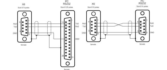
Interface cable between
the PC and the servo amplifier
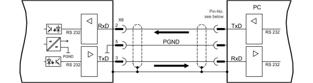
(View: looking at the built-in SubD connector, i.e. the solder side of the SubD plug on the cable)
Installation under WINDOWS 95(c) / 98 / 2000 / ME / XP / NT
You can install the setup software directly from the enclosed CD-ROM (call up SETUP.EXE).
Switch-on:
Switch on your PC-AT and the monitor.
When the boot phase is finished,
the Windows user-interface will appear on the screen.
Installation:
Autostart function activated:
Insert the CD-ROM into a free
drive. A window with the start screen opens. There you find a link to the
setup software DRIVE.EXE. Click it and follow the instructions.
Autostart function deactivated:
Insert the CD-ROM into a free drive. Click
on START (task bar), then on Run. Enter the program call: x:\index,.htm
or x:\autorun.exe (x = correct CD drive letter).
Click OK and proceed as
described above.
Operation
The setup software is basically used in the same way as other Windows programs.
Use a decimal point as the decimal symbol, do not use a comma.
Please note that, after an alteration in a parameter on a screen page, you must first click on APPLY, so that the parameter is transferred to the RAM of the servo amplifier. Only then you should leave the page. If a reset of the servo amplifier is necessary to activate a function, this will be recognized by the setup software, which will make a reset after a software confirmation request.
The currently valid data set must be saved in the EEPROM of the servo amplifier, in order to be permanently stored. So execute the Save Data to EEPROM function on the "Amplifier" page before you switch off the servo amplifier or quit processing the data set.
Values appearing in red on the screen pages designate parameters that are intended for advanced users only.
Function keys
|
Function key |
Function |
Comment |
|
F1 |
Help |
Contextual help |
|
F2 |
reserved |
reserved |
|
F3 |
reserved |
reserved |
|
F4 |
Jog Mode |
Starts the Jog Mode. The drive operates under the parameters that are pre-selected on the "Homing" page while the F4 key is pressed. |
|
F5 |
DC |
The drive operates under the parameters that are pre-selected on the "Oscilloscope/Service" pages. |
|
F6 |
Speed |
|
|
F7 |
Torque |
|
|
F8 |
Reversing |
|
|
F9 |
Stop (OFF) |
Brakes off the drive movement. The response of the drive varies according to the operating mode that is valid at the moment:
OPMODE=0
OPMODE=2
OPMODE=8 |
|
F12 |
Disable |
Software disable |
|
Shift F12 |
Enable |
Software enable |
|
|
Stopping the axis by using F9 or F12 does not ensure personal safety unless further measures are implemented. For safety, operate the ENABLE signal for the amplifier through a button that has to be confirmed, and ensure that the EMERGENCY STOP function is active for this axis. |