Screen page "Homing"
The reference traverse (homing) is an absolute task, that is used to zero
the drive for subsequent positioning operations. You can choose between
various types of homing.
After homing, the drive reports "InPosition" and then enables the position
controller in the servo amplifier.
|

|
Take care that the zero point of the machine (reference point) is in a
position that permits the subsequent positioning operations. The software
limit-switches that were set as parameters may be ineffective. The axis
could move on to the hardware limit-switch or even the mechanical stop.
There is a risk of damage.
If the reference point (zero point of the machine) is approached with excessive
velocity, for instance because of high moments of inertia, it may be overshot
and, in the worst case, move on to the hardware limit-switch or even the
mechanical stop. There is a risk of damage.
The position controller cannot be operated without first making a reference
traverse (homing).
A homing/reference traverse must be made after the 24V
auxiliary voltage has been switched on.
The start signal must not be removed
during homing.
The start signal must remain present until the "InPosition" message appears.
The SW-enable is set automatically when homing starts. Homing will only
be started in OPMODE 8. However, the SW-enable is set in all OPMODES. The
drive can therefore be accelerated by an analog setpoint that is applied,
if the START command is executed in OPMODES1 or 3.
|
Start
|
ASCII: MH
|
Default: -
|
valid for OPMODE 8
|
Radio button to start homing.
Stop
|
ASCII: STOP
|
Default: -
|
valid for all OPMODES
|
Radio button to stop (cancel) the homing. The SW-enable remains set!
Reference traverse
|
ASCII: NREF
|
Default: 0
|
valid for OPMODE 8
|
You can choose which type of reference traverse should be performed. A
preset zero-point offset (screen page "Encoder" is taken into account for the
position output and display.
Exception: Homing 5 — in this case the true
current position is displayed.
You can shift the zero-crossing point of
the motor shaft within one turn, at will, by using the "NI offset" parameter
(screen page "Encoder").
Zero-point recognition: the reference point is set to the first zero-crossing
point of the feedback unit (zero mark) after recognition of the reference
switch transition. Two-pole resolvers and all encoders have just one zero-crossing
per turn, so the positioning at the zero mark is unambiguous within a motor
turn. For 4-pole resolvers there are two zero-crossings per turn, and for
6-pole resolvers there are three zero-crossings.
If the transition of the
reference switch lies very close to the zero-crossing point of the feedback
unit, then the positioning to the zero mark can vary by one motor turn.
|

|
The repetition accuracy of homing operations that are made without zero-point
recognition depends on the traversing speed and the mechanical design of
the reference switch or limit-switch.
|
|
Homing 0
|
Sets the reference point to the setpoint position (the following error
is lost).
|
|
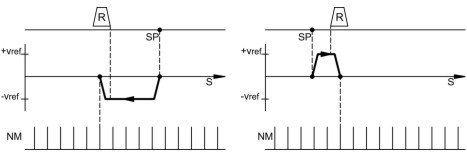
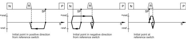
Homing 1
|
Traverse to the reference switch with zero-mark recognition.
|
In this case, a reference traverse can also be made without hardware limit-switches.
The precondition is one of the initial situations shown below:
|
|
negative traverse,
positive rotation
|
negative traverse,
negative rotation
|
|
|
|
|
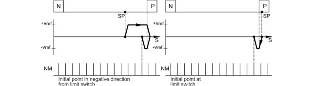
Homing 2
|
Move to hardware limit-switch, with zero-mark recognition. The reference
point is set to the first zero-crossing of the feedback unit (NM, zero
mark) beyond the limit-switch.
|
|
Homing 3
|
Move to reference switch, without zero-mark recognition. The reference
point is set to the transition of the reference switch.
|
|
Homing 4
|
Move to hardware limit-switch, without zero-mark recognition. The reference
point is set to the transition of the hardware limit-switch.
|
|
Homing 5
|
Move to the next zero-mark of the feedback unit. The reference point is
set to the next zero-mark of the feedback unit.
|
|
Homing 6
|
Sets the reference point to the actual position (the following error is
not lost).
|
|
Homing 7
|
Move to mechanical stop, with zero-mark recognition. The reference point
is set to the first zero-crossing of the feedback unit (NM, zero mark)
beyond mechanical stop.
The pulse current is set by the parameter REF.-IPEAK on the
screen page "Current controller".
|
|
Homing 8
|
Drives to an absolute SSI position. At the start of the homing run, a position
is read in from the SSI input (GEARMODE=7), converted according to the
scaling factors GEARI and GEARO and the reference offset, and then used
a the target position.
|
On the following pages you can find the paths traversed during homing types
1 to 5 for every
possible initial situation (positive rotation, negative
and positive directions of motion).
The meanings of the abbreviations in the drawings are:
|
N
|
limit-switch NSTOP
|
P
|
limit-switch PSTOP
|
SP
|
start position
|
|
R
|
reference switch
|
vref
|
preset velocity
|
NM
|
zero mark of the resolver
|
Homing 1
|

|
Warning!
Before starting homing, check the safety of the system, since the
load may move, even if the limit-switches are disconnected or defective.
The
limit-switch functions 2, PSTOP and 3, NSTOP must be activated to achieve the full homing functionality.
|
Homing with reference switch, negative direction of motion, positive rotation,
with zero-mark
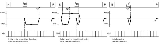
Homing with reference switch, positive direction of motion, positive rotation,
with zero-mark

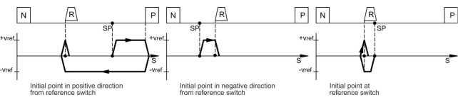
Homing 2
|

|
Warning!
Hardware limit-switches must be present and connected.
The limit-switch functions 2, PSTOP
and 3, NSTOP must be switched on.
|
Homing without reference switch, negative direction of motion, positive
rotation, with zero-mark
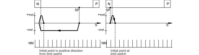
Homing without reference switch, positive direction of motion, positive
rotation, with zero-mark
Homing 3
|

|
Warning!
Before starting homing, check the safety of the system, since the
load may move, even if the limit-switches are disconnected or defective.
The
limit-switch functions 2, PSTOP and 3, NSTOP must be activated to achieve the full homing functionality.
|
Homing with reference switch, negative direction of motion, positive rotation,
without zero-mark
Homing with reference switch, positive direction of motion, positive rotation,
without zero-mark
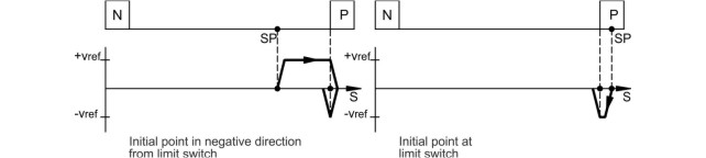
Homing 4
|

|
Warning!
Hardware limit-switches must be present and connected.
The limit-switch functions 2, PSTOP
and 3, NSTOP must be switched on.
|
Homing without reference switch, negative direction of motion, positive
rotation, without zero-mark
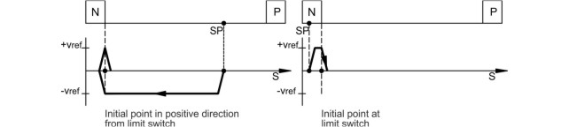
Homing without reference switch, positive direction of motion, positive
rotation, without zero-mark
Homing 5
|

|
Behavior for successively repeated starts of Homing 5:
The position controller
can only hold the motor in the zero position by passing the zero mark by
± 1 count. On a repeated start of Homing 5, depending on the position (1
count in advance of or 1 count behind the zero-mark) and the count direction,
the movement may be a full motor turn!
|
Homing without reference switch, negative direction of motion, positive
rotation, with zero-mark

Homing without reference switch, positive direction of motion, positive
rotation, with zero-mark

Homing 7
|

|
Warning!
Using this type of homing run can damage the mechanical stop on the machine.
The peak current Ipeak and the continuous current Irms are limited for
the duration of the homing run.
A more severe limiting of the current is possible. (see parameter Ref.-Ipeak).
|
Homing to mechanical stop, negative direction of motion, positive rotation,
with zero-mark

Homing to mechanical stop, positive direction of motion, positive rotation,
with zero-mark

Direction of motion
|
ASCII: DREF
|
Default: 0
|
valid for OPMODE 8
|
Determines the direction of motion for homing. The setting "distance-dependent"
is only relevant for Homing 5 (within one turn). In this case, the direction
is chosen to give the shortest distance to the zero-mark. This parameter
also defines the direction of motion for a Modulo type of axis.
v for homing
|
ASCII: VREF
|
Default: 0
|
valid for OPMODE 8
|
Determines the velocity for the homing operation. The sign is automatically
fixed by the direction of motion that is selected. The dimension is set
by VUNIT .
Accel. ramp
|
ASCII: ACCR
|
Default: 10 ms
|
valid for OPMODE 8
|
The acceleration ramp for the homing operation. The dimension is set by
ACCUNIT. Entry e.g. in milliseconds (1 ... 32767 ms). The ramp is also valid for
constant velocity mode.
Decel. ramp
|
ASCII: DECR
|
Default: 10 ms
|
valid for OPMODE 8
|
The deceleration (braking) ramp for homing. The dimension can be set by
ACCUNIT. Entry e.g. in milliseconds (1 ... 32767 ms). The ramp is also valid for
constant velocity mode. This deceleration ramp is only used if the operating
mode allows it. For homing to a hardware limit-switch, the emergency ramp
is used.
Offset
|
ASCII: ROFFS
|
Default: 0
|
valid for OPMODE 8
|
With the reference offset you can assign an absolute position value other
than 0 to the reference point. With an offset for the reference position
you are not actually making a physical change, but the offset is used as
a reference value within the position control of the servo amplifier. Homing
to the reference switch will then not finish at zero, but at the preset
reference offset value. The reference offset must be set before homing
is started. The dimension is set by PUNIT. An alteration of the offset only
takes effect after a new homing operation.
The parameter "Resolution" must be set
correctly for your application.
Jog mode
Jog mode is defined as an endless motion at a constant velocity. This type
of operation can be started without a reference point being set. The hardware
limit-switches are monitored. Software limit-switches are only monitored
if a reference point has been set. Acceleration and deceleration ramps
are taken from the settings for homing.
|

|
When the function "Jog mode" is started, the SW-enable is set automatically.
The Function "Jog mode" is only started in OPMODE 8. However, the SW-enable
is set in all OPMODES. The drive can therefore be accelerated by an analog
setpoint that is applied, if the START command is executed in OPMODES1
or 3.
|
v
|
ASCII: VJOG
|
Default: 0
|
valid for OPMODE 8
|
Determines the velocity for jog mode. The sign that is entered determines
the direction of movement. Before starting the jog mode, the velocity value
must be taken on. The dimension is set by VUNIT .
F4
|
ASCII: MJOG
|
Default: -
|
valid for OPMODE 8
|
Start the jog mode by pressing the function key F4. The drive moves with
the preset velocity in the direction, which is indicated by the sign of
the velocity for the jog mode "v", as long as the function key is pressed.
If a communication error occurs while pressing the button, the drive stops
with the emergency deceleration ramp.