| Feedback |
This documentation explains the use of the setup software DRIVEGUI.exe for setting parameters and configuring servo amplifiers. Detailed descriptions of functions and parameters are located in the Object Reference Guide (part of the software's Online Help system).
The setup software must be installed on a personal computer (PC). The PC is connected to the servo amplifier by a communication cable. The setup software initiates the communication between PC and servo amplifier.
With very little effort you can alter parameters and instantly observe the effect on the drive, since there is a continuous (online) connection to the amplifier. At the same time, important actual values are read out from the amplifier and displayed on the monitor of the PC (oscilloscope functions).
Any interface modules (expansion cards), which may be built into the amplifier, are automatically recognized and the additional parameters required for position control or motion-block definition are made available.
You can save sets of data on data media (archiving), and load them again. You can also print out the data sets.
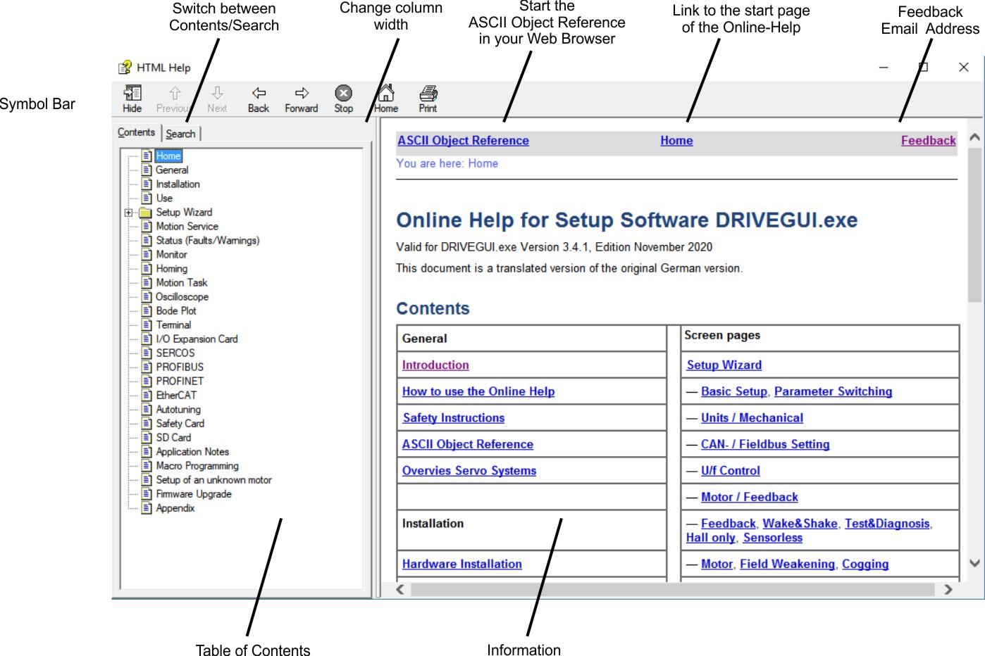
The Online-Help can be used like an Internet website with links, navigation frame and back/forward buttons.
All frames are visible only, if you started the online help from the menu bar of the setup software. If you use Context Help or function key F1, the fulltext search frame and the text frame are visible only. In this case you can restart the help system by clicking the symbol "Home".
The button Show/Hide activates/deactivates the full text search frame. Use asterisk or question mark (? or *) as usual with Windows search.
If, despite the SHOW button being pressed, the window in which you enter a search term does not open the first time the help system is called, the search-window column width is preset to “0” by the operating system. In this case, modify the column width by dragging the gray column separator at the left edge of the window, a process with which you should be familiar from WINDOWS.
|
Symbol |
Bedeutung |
|---|---|
|
|
Indicates a hazardous situation which, if not avoided, will result in death or serious injury. |
|
|
Indicates a hazardous situation which, if not avoided, could result in death or serious injury. |
|
|
Indicates a hazardous situation which, if not avoided, could result in minor or moderate injury. |
|
|
Indicates situations which, if not avoided, could result in property damage. |
|
|
This symbol indicates important notes. |
|
|
Warning of a danger (general). The type of danger is specified by the text next to the symbol. |
|
|
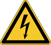
Warning of danger from electricity and its effects. |
|
|
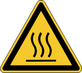
Warning of danger from hot surface. |
|
|
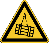
Warning of danger from suspended loads. |
|
|
Warning of danger from automatic start. |
This section helps you to recognize and avoid dangers to people and objects.
Read the documentation!
Read the available documentation for servo amplifier and servo motor before installation and commissioning. Improper handling of the devices can cause harm to people or damage to property. The operator of systems using the must require that all personnel who work with the drive read and understand the manual before using the devices.
Perform a risk assessment!
The manufacturer of the machine must generate a risk assessment for the machine, and take appropriate measures to ensure that unforeseen movements cannot cause injury or damage to any person or property. Additional requirements on specialist staff may also result from the risk assessment.
Specialist staff required!
Only properly qualified personnel are permitted to perform such tasks as transport, installation and setup. Qualified specialist staff are persons with expertise in transport, installation, assembly, commissioning and operation of electrotechnical equipment.
The qualified personnel must know and observe ISO 12100 / IEC 60364 / IEC 60664 and national accident prevention regulations.
Check Hardware Revision!
Check the Hardware Revision Number of the product (see product label). This number is the link between your product and the manual, it must match the Hardware Revision Number on the cover page of the manual.
Pay attention to the technical data!
Adhere to the technical data and the specifications on connection conditions (rating plate and documentation). If permissible voltage values or current values are exceeded, the devices can be damaged. Unsuitable motor or wrong wiring will damage the system components. Check the combination of drive and motor.
Observe electrostatically sensitive components!
The servo amplifier contain electrostatically sensitive components which may be damaged by incorrect handling. Electrostatically discharge your body before touching the device. Avoid contact with highly insulating materials (artificial fabrics, plastic film etc.). Place the servo amplifier on a conductive surface.
Automatic restart
The drive might restart automatically after power on, voltage dip or interruption of the supply voltage, depending on the parameter setting. Risk of death or serious injury for humans working in the machine.
If the parameter AENA is set to 1, then place a warning sign to the machine (Warning: Automatic Restart at Power On) and ensure, that power on is not possible, while humans are in a dangerous zone of the machine. In case of using an undervoltage protection device, you must observe EN 60204-1:2006 chapter 7.5.
Hot surface!
The surfaces of the servo amplifiers can be hot in operation. Risk of minor burns!
The surface temperature can exceed 80°C. Measure the temperature, and wait until the motor has cooled down below 40°C before touching it.
Earthing!
It is vital that you ensure that the devices are safely earthed to the PE (protective earth) busbar in the switch cabinet. Without low-resistance earthing no personal protection can be guaranteed and there is a risk of death from electric shock.
Leakage Current!
Since the leakage current to PE is more than 3.5 mA, in compliance with IEC61800-5-1 the PE connection must either be doubled or a connecting cable with a cross-section >10 mm² must be used. Deviating measures according to regional standards might be possible.
High voltages!
Ensure that the switching cabinet remains closed while the devices are in operation.
Do not remove any connectors during operation as this may cause electrical arcing, resulting in personal injury and damage to contacts. DC Bus link connections can carry dangerous voltage levels several minutes after the line voltage has been switched off (self-discharge time).
Wait at least seven minutes after disconnecting the servo amplifier from the main supply power before touching potentially live sections of the equipment (such as contacts) or removing any connections. Capacitors can have dangerous voltages present up to seven minutes after switching off the supply power. Always measure the voltage in the DC bus link and wait until the voltage is below 50 V before handling components.
Reinforced Insulation!
Thermal sensors, motor holding brakes and feedback systems built into the connected motor must have reinforced insulation (according to IEC61800-5-1) against system components with power voltage, according to the required application test voltage.
Check parameters before enabling the servo amplifier
Date saved on SD cards are not safe against unintended third-party changes. After loading a data set, you must always check the parameters before you enable the servo amplifier.
Never modify the servo amplifiers!
It is permissible to use the setup software to alter the settings of the servo amplifier. Any other alterations will invalidate the warranty. Opening the housing causes loss of warranty and all certificates become unvalid.
Warning signs are added to the device housing. If these signs are damaged, they must be replaced immediately.
Servo amplifiers are safety components that are built into electrical plant or machines, and can only be operated as integral components of such plant or machines.
The manufacturer of the machine must generate a risk assessment for the machine, and take appropriate measures to ensure that unforeseen movements cannot cause injury or damage to any person or property.
If the servo amplifiers are used in residential areas, in business and commercial areas, or in small industrial operations, then additional filter measures must be implemented by the user.
Cabinet and Wiring
The servo amplifiers must only be operated in a closed control cabinet, taking into account the ambient conditions defined in the instructions manual. Ventilation or cooling may be necessary to keep the temperature within the cabinet below 40°C.
Use only copper conductors for wiring. The conductor cross-sections can be derived from the standard IEC 60204 (alternatively for AWG cross-sections: NEC Table 310-16, 60°C or 75°C column).
Power supply
Syxx0 : Servo amplifiers in the S3xx0/S7xx0 series (overvoltage category III acc. to EN 61800-5-1) can be supplied from 1-phase or 3-phase grounded (earthed) industrial supply networks (TN-system, TT-system with grounded neutral point, no more than 42kA symmetrical rated current at 110V-10% to 230V+10%).
Syxx6 : Servo amplifiers in the S3xx6/S7xx6 series (overvoltage category III acc. to EN 61800-5-1) can be supplied from 3-phase grounded (earthed) industrial supply networks (TN-system, TT-system with grounded neutral point, no more than 42kA symmetrical rated current at 208V-10%, 230V, 240V, 400V or 480V+10%).
Periodic overvoltage between phases (L1, L2, L3) and the housing of the servo amplifier must not exceed 1000V crest.
In accordance with IEC 61800, voltage spikes (< 50µs) between phases must not exceed 1000V. Voltage spikes (< 50µs) between a phase and the housing must not exceed 2000V.
Motors
The servo amplifiers are exclusively intended for driving suitable brush less synchronous servomotors, asynchronous motors and DC motors with control of torque, speed and/or position.
The rated voltage of the motors must be at least as high as the DC bus link voltage divided by √2 produced by the servo amplifier (UnMotor ≥ UDC/ √2).
Safety
The STO function is exclusively intended to provide functional safety, by preventing the restart of a system. To achieve this functional safety, the wiring of the safety circuits must meet the safety requirements of IEC 60204, ISO 12100, IEC 62061 respectively ISO 13849-1.
In case of single channel control: if STO is automatically activated by a control system, then make sure that the output of the control is monitored for possible malfunction.
To achieve PL e or SIL CL3, the safe switching of the pulse inhibitor must be tested periodically by analyzing the feedback signal from the safety control.
Observe the user documentation for safety cards S3 / S4 when you use a safety expansion card.
Other use than described in chapter Use as Directed is not intended and can lead to damage of persons, equipment or things.
The use of the servo amplifier in the following environments is prohibited:
Commissioning the servo amplifier is prohibited if the machine in which it was installed,
The control of holding brakes by the servo amplifier alone may not be used in applications, where functional safety is to be ensured with the brake.
The STO function must not be used if the drive is to be made inactive for the following reasons :
Integrated in this Online Help is an Object Reference Guide of the servo amplifier's firmware. All functions and parameters are described there with full details.
The reference guide starts in a single frame: ASCII Object Reference
This topic provides a quick lesson in servo system - an overview of what it is and how it works.
What is a Servo System?
A servo system essentially comprises an intelligent servo drive and a servo motor that operates with a PLC or CNC to perform complex, specialized moves in one or more directions, or axes. These complex and specialized moves, which are needed in the automation of industrial tasks, are collectively known as motion control.
Servo systems are applied in many different field for automation - in the motor industry, the petrol industry, the textile industry, in packaging systems, warehousing systems and so on.
Closed Loop Servo Systems
In a servo system, feedback information - motor position and motor velocity is sent from the feedback unit of the motor back to the servo amplifier. The servo amplifier analyzes the feedback, makes adjustments as needed, and generates new currents to bring the motor to the commanded velocity. This cycle constantly repeats itself in a closed loop. A closed loop that controls the position of the shaft or load is called a position loop. A closed loop that keeps the velocity of the motor on the commanded value is called a velocity loop.
Servo System Components
A servo system consists of:
|
Servo motor |
A servo motor moves machinery in a single axis of motion. Electrical motors are driven by magnetic fields. Motors have a stationary field generated by the magnets of the motor and a rotating or movable field called stator winding or armature. They operate on the principles of synchronous motors. All rotary motors have some type of bearing that supports the rotor at each end. Every motor has at least two magnetic motor poles, normally four or six. The servo amplifier generates the current in the stator so that a controllable torque is available at the shaft. The servo motors turn (travel) in two directions - positive and negative. Two forms of angular measurement are commonly used in motion control - degree measurement and radian measurement, where 360 degrees constitute one revolution or 2π radians. The servo amplifier operates with standard synchronous servo motors as well as with direct drive motors (rotary or linear), induction machines and DC motors. For more information about these motors see the motor manuals. Motor Stabilizing Stabilizing (tuning) the motor is a fundamental task in achieving best system performance. To stabilize a motor, you must set up initial values for and adjust several motion parameters using . These parameter settings compensate for the difference between the actual motion and the commanded motion - getting the actual as close to the commanded as possible, with minimal oscillation and noise. This difference is called following error. Observe the application notes for Setup of unknown motors. |
|
Load |
The load is the machinery and equipment that each motor drives. It is everything connected to the output shaft of a motor, including the shaft itself. A motor must be appropriately sized to its load to ensure the motor is powerful enough to carry out your automation tasks. A servo system delivers and converts motion to a load via one or more of the following mechanical techniques: |
|
Feedback device |
Every closed-loop servo system needs at least one device to return feedback information from each motor (or load) to servo amplifiers . Depending on the feedback device, feedback is transmitted back to the servo drive in the form of digital signals or analog signals. Two types of feedback devices are supported:
|
|
Servo amplifier |
The servo amplifiers comprise a three-phase, power supply, and high-performance control unit all housed in a single enclosure. The several control loops are realize totally digital in the micro controller. |
Servo motors are available with these feedback units:
n a closed-loop feedback system, the innermost loop is the commutation loop, which monitors the motor's rotor and ensures that it keeps spinning.
Outer loops are: Position loop, Velocity loop and Current loop Velocity information and the velocity loop are derived from (are computed based on) position information.
The current loop is also known as a torque loop, since amplitude of the electrical current is directly proportional to torque. Torque is force applied in an axis of rotation.
Resolver
A resolver can be thought of as a transformer whose output is unique for any given shaft position (an absolute position feedback). The transformer is driven with a sinewave reference signal. Two AC signals are returned from the resolver into the Sine and Cosine inputs. All three of these sinewave signals are low-level and susceptible to noise.
The servo amplifier can use single (two poles) or multi-speed (multiple poles) resolver feedback to calculate primary position, velocity, and commutation information.
Encoder
Encoders direct pulses of light, from a light source at the motor or load, to photo detectors through an encoded disk. These light pulses are then converted into digital feedback information. There are two general types of encoders - rotary and linear. Rotary (rotating disk) encoders are typically mounted to the motor shaft. Linear encoders are typically mounted to the load.
Overview
Motion operations are universally embodied in a graph called the motion profile. Understanding and using motion profiles to define your motion application is an important part of achieving best system performance.
The motion profile plots one or more motion operations and measures it against time.
Commanded motion: the motion that is supposed to happen ideally and precisely, without error, when the motor executes a velocity or position command
Actual motion: the motion that really happens in the motor, when a velocity or position command is executed
Closing the Gap between Setpoint and Actual
Best system performance is achieved when you can stabilize or "dampen" the difference or "close the gap" between the commanded motion and the actual motion. This difference is called following error. Stabilizing the servo system means setting the relevant parameters in the servo amplifier, to get as close to the commanded position as possible.
Basic Motion Profile Characteristics
Commanded and actual motion profile shapes have the following characteristics that are also universal to all motion operations:
|
Characteristic |
Meaning |
|---|---|
|
Moving |
Moving refers to the execution of a motion instruction that makes the motor move. A motion profile's moving portion represents most of the profile - the motion itself. The motor is considered moving for as long as the motion controller is commanding new positions. The point at which motion stops is known as the target position. |
|
In Position |
When a motion command stops executing, and the motor slows to within a few counts of its target position, the motor is considered to be stopped, or "In Position." A range of positions, typically plotted in a motion profile, represents in position. That is, In Position is signaled when the motor gets close enough to the target position -- within its In-Position range that you have specified, via its parameter. An In-Position signal is often used to make sure the motor stops before the machinery continues its operation. |
Overview
Another important task in achieving best system performance is setting certain motion limits and ranges of operation to protect equipment from damage and to optimize operational efficiency.
Two Types of Settings
There are two types of settings for motion limits and ranges of operation:
|
Type of Setting |
Meaning |
|---|---|
|
Fault limit |
Fault limits are settings that signal errors when certain limits on motor movement, such as speed and position, as well as electrical current, are exceeded. Fault limits are designed to protect equipment from damage and can cause the drive and motor to shut down. For example, every motion control system has hardware limit switches, which are used in the position loop to set a limit on how far the actual motor position can deviate from the commanded position before a fault is signaled. You may also program software limits. The difference, or gap, between commanded position and actual position is known as following error. Such a limit protects against motor runaway and stalling. |
|
Tolerance band |
Tolerance bands are set and specify the safe, efficient physical ranges for the equipment. Some of these tolerance bands do the following:
|
Overview
If the servo amplifier is operated with motion tasks under position control, different acceleration/deceleration profiles can be chosen. It depends on the mechanical structure of the machine and the required dynamical quality, which profile should be chosen. If the machine tends to sway (e.g. robot arm), sine² would be the best choice. Here the torque is altered linear and the velocity characteristic becomes square. This reduces the excitation to sway. Disadvantage of this profile is the double up of the acceleration/deceleration time.
If the machine is mechanically stiff and there are high requirements in dynamics, the linear profile should be chosen. This leads to a torque step at the beginning and the end of each acceleration/deceleration ramp.
The following table describes the two fundamental acceleration and deceleration types, linear and square. A motion profile may accommodate a combination of these two types.
|
Type |
Description |
|---|---|
|
Trapezoidal |
Trapezoidal is a rate of acceleration and deceleration that represents a steady speed-up and slow-down. |
|
Sine² |
To limit any jolting, the drive is accelerated/decelerated within the acceleration time along an acceleration ramp without any discontinuities. The resulting speed characteristic corresponds to a sine² curve. |
Further acceleration curves are stored in profile tables. You can create your own profile tables
|
Stay Connected with Kollmorgen       
|
Copyright © 2020 |
|