| Feedback |
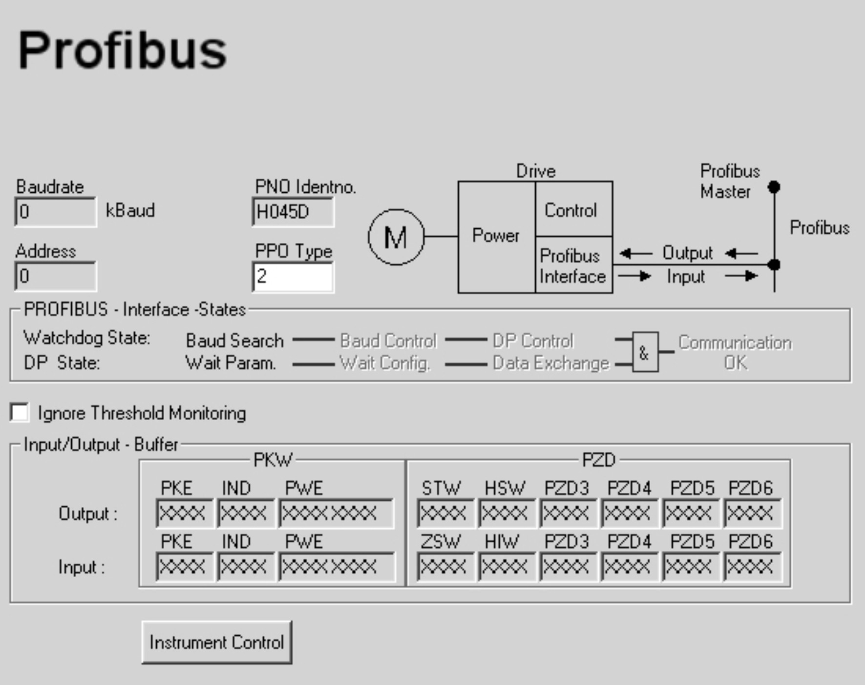
This screen is avalable only if a PROFIBUS expansion card is inserted into the servo amplifier.
The PROFIBUS-specific parameters, the bus status, and the data words in the transmit and receive directions (as seen by the bus-master) are displayed on this screen page. This page is helpful when searching for errors and commissioning the bus communication.
| Baudrate |
The baud rate that is given by the PROFIBUS master is shown here |
| PNO Identno |
The PNO identification is the number for the amplifier in the list of ID-numbers of the PROFIBUS user organization. |
| Address |
Station address of the amplifier (Setup see CAN/Fieldbus) |
| PPO type |
The amplifier only supports PPO-type 2 of the PROFIDRIVE profile. |
| Interface states |
Shows the present status of the bus communication. Data can only be transferred across the PROFIBUS when the “Communication OK” message appears. |
| Input |
The last bus object that was received by the master. |
| Output |
The last bus object that was sent by the master. |
.
|
|
The data for input/output are only transferred, if the threshold monitoring for the servo amplifier has been activated in the master’s hardware configuration. |
The following parameters configure the amplifier for the Profibus interface.
EXTWD (PNU 1658)
With this parameter, the observation time (watch dog) for the fieldbus-slot communication can be set (setup see CAN/Fieldbus). The observation is only active, if a value higher than 0 is assigned to EXTWD (EXTWD=0, observation switched off) and the output stage is enabled. If the set time runs out, without the watchdog-timer being newly triggered by the arrival of a telegram, then the warning n04 (response monitoring) is generated and the drive is stopped. The amplifier remains ready for operation and the output stage enabled. Before a new driving command (setpoint) is accepted, this warning must be deleted (function CLRFAULT or INxMODE=14).
ADDR (PNU 918)
With this command, the node address of the amplifier is set (setup see CAN/Fieldbus). When the address has been changed, all parameters should be saved to the EEPROM and the amplifier switched off and on again.
AENA (PNU 1606)
With this parameter, the state of the software-enable after switch-on can be defined (setup see BASIC Setup). The software-enable allows an external control to enable/disable the output stage. For amplifiers with analog setpoints (OPMODE=1,3) the software-enable is set automatically after switch-on and the devices are ready for operation immediately (if hardware-enable is present). For all others, software-enable will be set to the value of AENA. The variable AENA also has functionality when resetting the amplifier after an error (by digital input 1 or the CLRFAULT command ). If an error can be reset by the software, the software-enable is set to the value of AENA after the error is cleared. In this way the behavior of the amplifier after a software-reset is similar to after the drive is switched on.
INPT0 (PNU 1904)
With INPT0 a delay for the in-position message can be set (setup see TERMINAL). With the start of a motion task the in-position message is deleted and the monitoring of the position is activated after expiration of the adjusted time. This function is particularly important for positioning procedures within the in-position window. In this case the in-position message is delayed for a defined time.
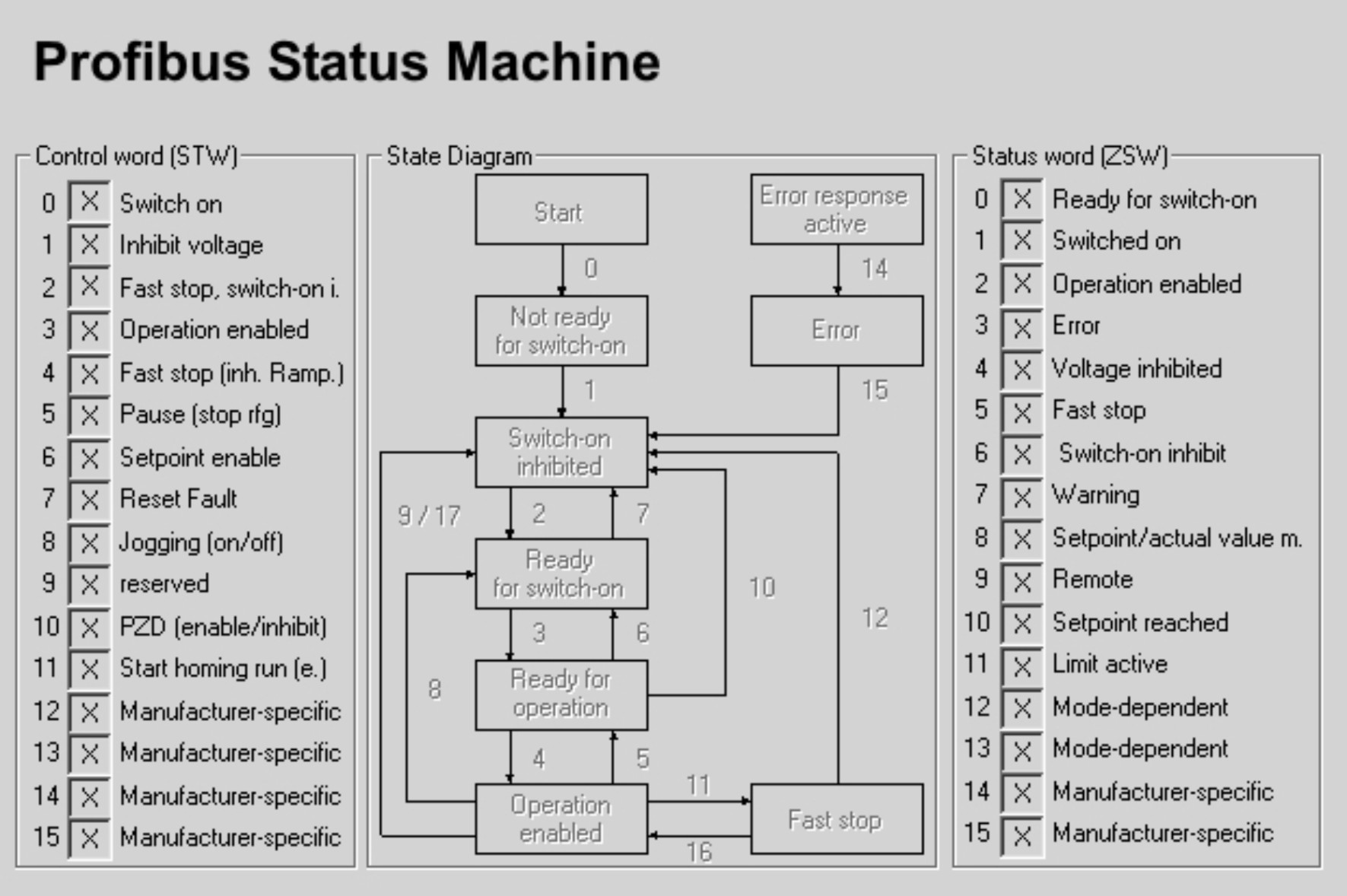
On this screen page the individual bits of the control word (STW) and the status word (ZSW) are shown. The device status resulting from the status word is visualized in the status machine. The current status is shown as black, all others are grey. Additionally the previous status is shown by emphasizing the number of the appropriate arrow.
|
Stay Connected with Kollmorgen       
|
Copyright © 2020 |
|