Setup Strategies
General
This chapter provides you with strategies for the commissioning of the
digital servo amplifier and the optimization of its control loops.
These strategies cannot be universally valid. You may have to develop your
own strategy, depending the specification of your machine.
However, the sequences that are presented here will help you to understand
the basic methodology.
Parameterization
|

|
The manufacturer of the machine must create a risk assessment for the machine,
and is responsible for the machine with regard to functional, mechanical
and personnel safety. This applies particularly to the initiation of movements
with the aid of commissioning-software functions.
The commissioning of the
servo drive with the aid of Setup software functions is only permitted
in combination with an interlock device according to EN 12100, that operates
directly on the drive circuitry.
|
-
The servo amplifier is installed, and all the necessary electrical connections
have been made.
-
The 24V auxiliary supply and the 208V...480V main power supply are switched
off.
-
A personal computer, with the commissioning software installed, is connected.
-
An interlock device according to EN12100 is connected.
-
The controls provide an LOW signal for the ENABLE input of the servo amplifier
(Terminal X3/15), i.e. the servo amplifier is disabled.
Switch on auxiliary supply
|
1.
|
Switch on the 24V auxiliary supply for the servo amplifier.
LED display: X.XX (firmware version)
BTB/RTO contact: open
After about 5 seconds:
LED display: YY. (amount of current, blinking point for CPU o.k.)
BTB/RTO contact: closed
|
|
2.
|
Switch on personal computer
|
|
3.
|
Start commissioning software
|
|
4.
|
Click on the interface (COM1... COM10) that is used for communication with
the servo amplifier.
The parameter are transmitted to the PC.
|
|
5.
|
Click on the radio button "SW-disable" at bottom right or press the function
key F12.
NO ENABLE now stands in the AXIS status field.
|
Basic setting
The servo amplifier remains disabled and the main power supply is switched
off.
|
1.
|
Set up basic parameters (address, ballast details, line/mains supply voltage
etc.):
- Click on the BASIC SETTINGS button
- Alter the fields, if necessary
-
Click on APPLY and then on OK
|
|
2.
|
Select motor:
- Click on the MOTOR button below the picture of the motor
-
Open the motor selection table, by clicking on the arrow in the field
NUMBER-NAME
- Click on the motor that is connected
- Click on APPLY
- Answer
the query about the brake
- Answer the query "Save to EEPROM/Reset" with
NO
(the data are in the RAM and will be permanently saved later)
|
|
3.
|
Select feedback (resolver, encoder):
- Click on the FEEDBACK button
- The
values that are displayed correspond to the default data that you have
loaded
for the motor.
- Alter the fields, if necessary
- Click on APPLY
and then on OK
|
|
4.
|
Set up the encoder emulation (ROD, SSI):
- Click on the ROD/SSI/ENCODER
button
- Select the desired encoder emulation
- Set up the corresponding
parameters in the right half of the window
- Click on OK
|
|
5.
|
Configure the analog inputs/outputs:
- Click on the I/O ANALOG button
- Select
the desired ANALOG-FUNCTION
- Set the scaling relative to 10V for the analog
input that is used.
- Set up the required output signals for AN OUT 1 and
AN OUT2
- Click on OK
|
|
6.
|
Configure the digital inputs/outputs:
- Click on the I/O DIGITAL button
-
Assign the required functions to the digital inputs (left half of window)
and enter the auxiliary variable X if it is necessary.
- Assign the required
functions to the digital outputs (right half of window)
and enter the
auxiliary variable X if it is necessary.
- Click on OK
|
|
7.
|
Save parameters:
- Click on the button
- Answer the query RESET AMPLIFIER
with YES
|
|
8.
|
Click on the radio button "SW-disable" at bottom right or press the function
key F12.
NO ENABLE now stands in the status field for AXIS
|
If you want to use the position control of the servo amplifier, then you
must enter the specific parameters for your drive:
|
1.
|
Axis type:
- Click on the POSITION button
- Click on the POSITION DATA button
- Select the axis
type (linear, rotary or modulo)
|
|
2.
|
For the axis type MODULO: enter the parameters Modulo-Start-Pos. and Modulo-End-Pos.
|
|
3.
|
Resolution:
- Enter the denominator and numerator for the resolution. Here
you adjust the path
traversed by the load in positioning units (length
unit for linear axes, or °mech.
for rotary axes) to match the number
of turns of the motor.
Only integer entries are permitted.
Example 1:
Ratio = 3.333 mm / turn
=> resolution = 10000/3 µm/turn (all other path
entries in µm)
or
=> resolution = 10/3 mm/turn (all other path entries in
mm)
Example 2: Ratio = 180 °mech./turn
=> resolution = 180/1 °mech./turn
(all other path entries in °mech)
|
|
4.
|
vmax:
- Enter the maximum traversing speed for the load that results from
the resolution
at the rated speed of the motor. The dimensional unit is
derived from the
resolution (°mech./sec or length units/sec).
Example 1:
resolution = 10000/3 µm/turn, nnom = 3000 turns/min
=> vmax = resolution
* nnom = 10000/3 * 3000 µm/min = 10 000 000 µm/min
or
=> vmax = resolution
* nnom = 10/3 * 3000 mm/min = 10 000 mm/min
Example 2: resolution = 180 °mech/turn,
nnom = 3000 turns/min
=> vmax = resolution * nnom = 180 * 3000 °mech/min
= 9000 °mech/s
|
|
5.
|
t_acc/dec_min:
- Enter the time in ms that the drive requires, with the
mechanically permissible maximum acceleration,
to accelerate from zero
speed to vmax.
|
|
6.
|
InPosition:
- Enter the window for InPosition. This value is used for the
InPosition message.
The dimensional unit is derived from the resolution
(°mech. or length unit).
Typical value: e.g. approx. resolution * 1/100
turn
|
|
7.
|
max. following error:
- Enter the window for the following error. This value
is used for the message
FOLLOWING ERROR. The dimensional unit is derived
from the resolution
(°mech. or length unit).
Typical value: e.g. approx.
resolution * 1/10 turn
|
|
8.
|
Save parameters:
- Click on the button
- Answer the query RESET AMPLIFIER
with YES
|
Optimization of the control loops
The basic setting must be finished.
Preparation
|
1.
|
OPMODE:
Set the OPMODE "1,analog speed" (screen page AMPLIFIER)
|
|
2.
|
Setp. function:
Set the analog I/O-function to "0,Xsetp=An In 1" (screen
page ANALOG-I/O)
|
|
3.
|
Save the parameters:
- Click on the button (screen page AMPLIFIER)
- Answer the query
RESET AMPLIFIER with YES
|
|
4.
|
An In 1:
Short-circuit the setpoint input 1 or apply 0V to it
|
|
5.
|
OSCILLOSCOPE:
Channel1: n_act Channel2: I_act (screen page OSCILLOSCOPE)
|
|
6.
|
Reversing mode:
Go to the screen page OSCILLOSCOPE/SERVICE/PARAMETER and set the
parameters for reversing mode to values that are safe for your machine,
also when the positioning control loop is switched off (approx. 10% of
the final limit speed).
|
|

|
During operation of the service function "Reversing mode" the analog setpoint
input is switched off and the internal positioning control is disabled.
Make sure that the individual motion of the selected axis is possible without
any hazard.
For safety, only operate the ENABLE signal of the amplifier
with an interlock switch, and check the EMERGENCY STOP function for this
axis.
|
Optimizing the current controller
Screen page CURRENT CONTROLLER
|
1.
|
If a suitable amplifier-motor combination is used, the current controller
will already have a stable setting for almost all applications.
|
|
2.
|
Ipeak:
- Reduce Ipeak to the rated value for the motor (protection of the
motor)
|
|
3.
|
Switch on the mains/line power.
|
|
4.
|
Provide the analog setpoint:
- Analog-In 1 = 0V
|
|
5.
|
Enable the amplifier:
- High signal at Enable input X3/15. In the AXIS status
field: NO SW-EN
- Click on the SW-Enable radio button. ENABLE now stands
in the AXIS status field.
The motor now stands under speed control, with
n=0 rpm. If the current controller is not stable in operation (motor oscillates
with a frequency clearly above 100Hz), please contact our applications
department.
|
Optimizing the speed controller
Screen page SPEED CONTROLLER
|
1.
|
SETP. -OFFSET:
Leave the amplifier enabled. If the axis is drifting, alter
the parameter Setp.-Offset until it stands still (or use the function AUTO-OFFSET).
|
|
2.
|
SETP. RAMP +/-:
The setpoint ramps are used to smooth the setpoint input (filter effect).
Set the mechanical
time constant for the complete system, i.e the rise time or ramp gradient
for the speed from 0 to ncmd.
As long as the ramps that are set are shorter
than the mechanical response time for the complete system, the response
speed will not be affected.
|
|
3.
|
LIMIT SPEED:
Set the desired final limit speed.
|
|
4.
|
KP/Tn:
Increase KP until the motor starts to oscillate (audible, and visible
on the oscilloscope) and then reduce KP again until the oscillations
have
definitely stopped and stability is assured.
Use the motor-specific default
value for Tn.
|
|
5.
|
Start reversing mode:
Start the reversing mode (F8, v1/v2 approx. +/-10% of nnom for the
motor).
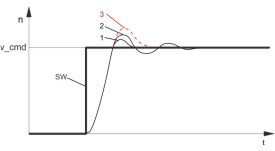
Observe the speed response on the oscilloscope. If the settings
are correct,
there must be a stable step response in both directions.
|
|
|
|
Diagram: Step response
n = speed
SW = setpoint
t = time
1 = optimum
2 = KP too high
|
|
6.
|
KP:
You can produce a fine tuning of the speed response by cautiously increasing
KP.
Aim: the smallest overshoot, but still retaining good damping.
A larger
total moment of inertia make it possible to use a larger value for KP.
|
|
7.
|
PID-T2:
You can dampen out disturbances, such as a small amount of play
in the gearing,
by increasing PID-T2 to about 1/3 the value of Tn.
|
|
8.
|
FEEDBACK:
You can further improve the smooth running by using FEEDBACK,
especially for
small drives with a low torque.
|
|
9.
|
End reversing mode:
Finish the reversing mode operation (F9).
|
Set up the correct, motor-specific value for Ipeak (current controller)
again. Start up reversing mode again, and observe the step response. If
there is any tendency to oscillation, reduce KP slightly.
Save the present parameter set in the EEPROM. Click on the button.
Optimizing the position controller
Screen page POSITION CONTROLLER
Preparation
|
1.
|
OPMODE:
Select OPMODE 8 (screen page AMPLIFIER)
|
|
2.
|
Position the load in a middle position:
The aim is, to use the Jog Mode
function to move the load to approximately the middle of the motion path.
-
Click on the POSITION button
- Click on the HOMING button
- Check that the parameter v
(Jog Mode) is set to 1/10 of the
preset speed limit vmax. The sign of
"v" determines the direction.
Alter the value if necessary, and click
on APPLY.
- Start the function JOG MODE by using the function key F4 and
move the load to approximately the middle of the motion path
WARNING:
If the drive moves in the wrong direction, release the F4 function key
and change the sign of the parameter "v" (Jog mode).
Use F4 again to
move the load to approximately the middle of the motion path.
|
|
3.
|
Set reference point:
- Set the homing type to activate "0, set reference point".
Start the homing run. The momentary position is set as the reference point.
-
Stop the homing run
- Click on the radio button "SW-disable" in the amplifier
window
|
|
4.
|
Define test motion blocks:
- Click on the POSITION button
- Click on the POSITION DATA button
-
Click on the MOTION TASK TABLE button and select task 1. Enter the
values from the table below,
then select task 2 and
enter the corresponding values.
|
|
|
|
Task 1
|
Task 2
|
|
units
type
s_cmd
v_cmd_source
v_cmd
t_acc_tot
t_dec_tot
ramp
next motion task
next
number
acc./dec.
start condition
APPLY/OK
|
SI
REL setpoint
+10% of total path
digital
10% of vmax
10 * t_acc/dec_min
10
* t_acc/dec_min
trapeze
with
2
to target position
immediately
click
|
SI
REL setpoint
-10% of total path
digital
10% of vmax
10 * t_acc/dec_min or
amax / 10
10 * t_acc/dec_min or amax / 10
trapeze
with
1
to target position
immediately
click
|
|
5.
|
Save parameters:
- Click on the button
- Answer the query RESET AMPLIFIER
with YES
|
Optimization
|

|
The starting of motion tasks with the aid of commissioning-software functions
is only permitted in combination with an interlock device according to
EN12100, that operates directly on the drive circuitry.
|
|
1.
|
Start motion task:
- Click on the POSITION button
- Select motion task 1 on screen
page POSITION DATA, click on START, motion task 1 is started and, because of the
definition
of the motion task sequence, the drive moves in position-controlled reversing
operation.
|
|
2.
|
Optimize parameters (Click on the POSITION DATA button)
|
|
3.
|
PID-T2, FEEDBACK:
The speed controller is not used in OPMODES4, 5 and 8.
The position controller includes an integral speed controller, that takes
on the preset parameters for PID-T2 and FEEDBACK from the screen page "SPEED CONTROLLER".
|
|
4.
|
KP, Tn:
If KP is set too low, the position controller tends to oscillate.
Use the value for the optimized speed controller for KP. Tn should be 2...3
times as large as the Tn value for the optimized speed controller.
|
|
5.
|
KV:
The acceleration behavior of the motor should be well damped (no tendency
to oscillation) with a minimum following error. If KV is larger, the tendency
to oscillation increases. If it is smaller the following error increases
and the drive becomes too soft. Vary KV until the desired response is achieved.
|
|
6.
|
FF:
The integral component of the control loop is in the position controller,
not the speed controller, so no following error results at Jog Mode (pure
proportional control). The following error that arises during acceleration
is affected by the FF parameter. This error is smaller if the FF parameter
is increased. If increasing FF does not produce any improvement, then you
can increase KP a little, to make the speed control loop somewhat stiffer.
|
If the drive does not run satisfactorily under position control, first
look for external causes such as:
-
mechanical play in the transmission chain (limits the KP)
-
jamming or slip-stick effects
-
self-resonant frequency of the mechanical system is too low
-
poor damping, drive is too weakly dimensioned
before trying to optimize the control loop again.