Screen page "Position Data"
For each one of the positioning tasks you must define motion tasks. These
motion tasks can be selected by a motion task number, and are stored in
the servo amplifier.
|
Motion task
|
Stored in
|
Precondition for storing
|
Comments
|
|
1...180
|
EEPROM
|
output stage disabled
|
permanently stored
|
|
192...255
|
RAM
|
none
|
volatile storage
|
When the servo amplifier is switched on, the RAM motion blocks 192...255
are automatically pre-loaded with the parameters of the EEPROM motion blocks
1...64.
Number
Entry of a motion task number, to start the motion task from the PC.
Motion task table
A new window appears, in which all motion tasks are represented in tabular
form.
All motion task parameters can be entered in the table directly. The following
operations are available:
The clipboard operations cut, copy and paste are only possible for complete
rows, i.e. for these operations the appropriate row must be selected. The
deletion is possible both, row- and cellwise. A line can be selected either
by clicking on the row number, or through the keyboard shortcuts <Shitft>+<Space>
(similar to Microsoft Excel). All Edit operations are available through
the Windows standard keyboard shortcuts.
Input via the screen page"Motion task parameters":
Double-clicking a line number in the table opens the screen page for the
associated motion task. The use of the dialogue "Motion task parameters"
in relation to older versions of the software changed concerning the buttons
"OK", and "Cancel".Compared to older versions of the software, the functions
of the buttons "OK" and "APPLY" have changed. By clicking these buttons,
the changes are no longer saved to the flash EEPROM but the values in the
associated table are changed instead. Writing the changes to the EEPROM
is possible with the buttons "OK" or "APPLY" on the screen page "Motion
task table"
Start
|
ASCII: MOVE
|
Default: -
|
valid for OPMODE 8
|
Start the motion task that has the number that can be seen in the NUMBER
field. The amplifier must be enabled (input X3/15 has a High signal).
|

|
The SW-enable is automatically set when the motion task starts. The motion
task is only started in OPMODE8. However, the SW-enable is set in all OPMODES.
The drive can therefore be accelerated by an analog setpoint that is applied,
if the START command is executed in OPMODES 1 or 3.
The motion task is not
started if the target position is beyond the defined SW-limit switches
(warning messages n06/n07 and n08)
|
Stop
|
ASCII: STOP
|
Default: -
|
valid for OPMODE 8
|
Stops the current motion task. The SW-enable remains set!
Axis type
|
ASCII: POSCNFG
|
Default: 0
|
valid for OPMODE 8
|
Here you select whether the axis is to be operated as a linear or a rotary
axis.
v_max
|
ASCII: PVMAX
|
Default: 100
|
valid for OPMODE 8
|
This parameter is used to adjust the maximum speed of movement to suit
the limits of the operative machinery. The calculation of the upper setting
limit depends on the final limit speed of the drive. The value that is
entered is used as a limit for the "v_setp" entry in the motion tasks.
During commissioning, you can limit the speed by using v_max (without changing
the setting for the motion blocks). A lower value of v_max overrides the
v_setp of the motion tasks.
t_acc/dec_min / a max
|
ASCII: PTMIN
|
Default: 1 ms
|
valid for OPMODE 8
|
A drive is always so dimensioned that it can provide more power than the
application requires. This parameter determines the limit for the maximum
mechanical acceleration time to v_max, that must not be exceeded by the
drive. This time is simultaneously valid as the minimum limit for the entry
"t_accel_tot" (acceleration time from 0 to v_setp) and "t_brake_tot" (braking
time from v_setp down to 0) for the motion tasks.
Depending on the setting
of acceleration unit you can enter either the acceleration time or the acceleration in the
dimensional unit that has been selected.
InPosition
|
ASCII: PEINPOS
|
Default: 4000
|
valid for OPMODES 4,5,8
|
Sets the InPosition window. Determines at which distance from the set position
the "InPosition" message should be reported. The drive moves precisely
to the target position.
Modulo-Start-Pos.
|
ASCII : SRND
|
Default : -231
|
valid for OPMODES 4,5,8
|
|
This parameter is used to define the start of the range of movement for
a modulo axis.
The end of the range is defined by the parameter Modulo-End-Pos.
|
Modulo-End-Pos.
|
ASCII : ERND
|
Default : 231-1
|
valid for OPMODES 4,5,8
|
This parameter is used to define the end of the range of movement for a
modulo axis.
The start of the range is defined by the parameter Modulo-Start-Pos.
Position register
A programmable register that can have various functions assigned to it.
Make
changes only while the amplifier is disabled + reset.
SW limit-switches 1 / 2
The software limit-switches from part of the monitoring functions of the
position controller.
|
SW limit-switch 1
|
The monitoring checks whether the actual position value is lower than the
preset value (the negative direction of travel is now inhibited – You have
to leave limit-switch 1 by moving in the positive direction. ).
|
|
SW limit-switch 2
|
The monitoring checks whether the actual position value is higher than
the preset value (the positive direction of travel is now inhibited – You
have to leave limit-switch 1 by moving in the negative direction.)
|
The drive brakes with the emergency ramp, and remains at standstill under
torque.
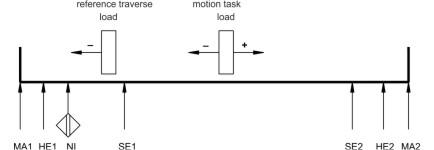
The principle of positioning the software limit-switch can be seen
in the diagram below:
|
|
Legend
MA1 : Machine stop, left
HE1 : Hardware limit-switch, left
NI : Zero pulse initiator
(reference)
SE1 : Software limit-switch 1
SE2 : Software limit-switch 2
HE2 :
Hardware limit-switch right
MA2 : Machine stop right
+ : Positive count direction
- :
Negative count direction
|
|
ASCII: SWCNFG (set, bit variable)
|
Default: 0
|
valid for all OPMODES
|
|
ASCII: (position)
SWE1, SWE2, SWE3, SWE4, SWE5
|
Default: 0
|
valid for all OPMODES
|
Configuration variables for the position register. SWCNFG is a binary-coded
bit-variable, and is transferred to the ASCII terminal program as a decimal
number.
Resolution
|
ASCII: PGEARI (numerator)
|
Default: 10000
|
valid for OPMODE 8
|
|
ASCII: PGEARO (denominator)
|
Default: 1
|
valid for OPMODE 8
|
The entry for the resolution of the motion tasks is in µm/Revolution. The
resolution can be defined at will, through the entries for the numerator/denominator.
Make
changes only while the amplifier is disabled + reset.
Examples:
An entry
of 10000/1 produces a resolution of 10 mm/turn
An entry of 10000/3 produces
a resolution of 3.333 mm/turn
Rotary table with geared motor, i = 31 (31
motor turns for one turn of the table)
– The entry 360/31 provides operation
with position entries in degrees, without rounding off.
The maximum range of movement is limited to +/- 2047 motor turns. If a
larger range (+/- 32767) is required, please consult our applications department.
GMT
Opens the graphical motion tasking.
Graphical motion tasking is an advanced
feature that lets you easily edit motion tasks with its graphical interface.
You can command multiple motions, process I/O, make decisions, add time
delays and modify drive process variables. The environment is easy to use,
allowing you to program in an intuitive flow-chart.
Motion tasking has been
supported by the amplifier since the product was introduced in 1998. In
its original form, motion tasking supported only chained moves in sequences
executed either once or in infinite loops. Graphical motion tasking extends
the capabilities of moiton tasking by adding looping, comparing (<, =,
>, etc.), calling functions and setting process variables.